Search the Community
Showing results for tags 'wiring diagram'.
Found 27 results
-
Hello, I'm working on a project that involves using a 1734-AENT remote IO module. In this project, I need to configure analog inputs, digital inputs, and digital outputs. Since I'm new to this field and have limited experience, I'm looking for guidance in creating a wiring diagram. If anyone in this community can provide assistance or perhaps share a basic wiring diagram template, I would greatly appreciate it. My primary focus is on generating the wiring diagram itself. Thank you for any help you can offer.
-
Dear All , i Have FX3uc-64mt/d plc. i am getting confused about its wiring . In manual it is mentioned that plc can be run on both sink and source while when i connect only OV to any pin it indicates the input high. although no signal is given to common terminal . can anybody explain me this phenomenon. thanks in advance.
-
According to picture 1, ''Piston A moves to the right. After the set time, K = 4, the normally closed timer T450 contacts open and the normally open timer T450 contacts close.'' But according to picture 2 After the power flow from Left power rail to right power rail, it should directly go to 2nd rung and cause the normally open timer T450 contacts to close only right? but why it will go back 1st rung and cause the normally closed timer T450 contacts to open? Anybody can help explain me regarding this. Thank You in advance
-
Good day all, I recently working an assignment to read analog data from sensors. I connected everything just as what the manual for sensor stated. My PLC is DVP20SX2 and the sensor data i want is 4-20mA. The analog sensor has two wires, Analog Output + and Analog Output GND. I connected the + to I0+ and the GND to the VI0-, but when I work online using the ISPSoft, I can't get any data. My doubt is the wiring. Can anyone guide me on this? Is my wiring wrong? does analog works the same as digital, where we have to connect to same COM?
-
HI all, Is there anything issue or wrong in thing connection ( added noise filter & fuse. )?
-
Hello! I have a problem with older equipment and I have to copy the data from it To connect to a hmi omron modelNT600M-DT211 what type of software should I use and if possible the connection scheme between hmi and laptop. Thank you!
-
Hello guys, I am new to PLC, most of what I know is on the programming side . I am trying to build a trainer for myself with a used Micrologix 1100. when I connect 24V DC to input side, the controller powers on. My understanding is that it should inly power on if I supply 110V AC to the power side . I think I might have damaged the device. Please advice
-

How to konw what type of ladder programming language is support by the plc compnay
forbidden_masud posted a topic in Other PLCs
Hey there, I have an "Italian safe CNG dispenser pm head". I googled about it and found that It is a plc board. So I searched how to program it. Then found it use ladder programming language. Now there are no tutorial or documentation about its programming. But I want to repair my damaged plc board. If I goto any technician they will charge a huge amount of money. So I thought I will repair it by my self. So need help about the software name its use and how can I program it. If any of you guys know about it please provide me your precious knowledge. Use this printerest link for see my pm head(plc board) https://i.pinimg.com/564x/0e/d6/6c/0ed66cb9a1065ab10a07e0b9aadc6f0d.jpg Thank you (TIA) Masud karim -

Allen Bradley 1764-24BWA Series B
marianosanchez posted a topic in Allen Bradley / Rockwell Automation
Hi everybody. I am looking for the schematic diagram of the power supply for the Allen Bradley 1764-24BWA series B. I did extensive search on google but could not find anything useful (only user manual of replacement parts). Thanks in advance. Cheers. -
Good dat i have a trouble of having this errors. Can i ask also a wiring config for keyence kz a500 to Pro face GP4301tw Thanks in advance
-
First time using Connected Components Workbench and am modifying an existing program, does anyone know why and how the original IO_EM_DI_ numbers have been changed and not just the alias'. When I right click and select properties for each tag it gives the address and says 'Read only cell' generated by the I/O wiring tool indicating the I/O channel to which the variable is wired' Any help would be great thanks!
-
Using a 1734-IB8 to Count Flow Meter Pulses
Jdeloz828 posted a topic in Allen Bradley / Rockwell Automation
Hello, -I'm considering using an AB 1734-IB8 to count input pulses from a Micro Motion flow meter transmitter and, since I'm very new to this stuff, would like a little guidance as to how/if this can be done. My first concern is the wiring. The manual for the transmitter shows this wiring diagram for the specific model I'm using. Here, B would represent the 1734-IB8 module. I'm not going to be using the analog loop. In addition to this wiring, terminals 9 & 10 on the transmitter will be wired to the same 24V and Common as my PLC modules. The 1734-IB8 manual shows this diagram for wiring. Should I consider the pulse output of the transmitter as a 3-wire device, connect terminal 3 of the transmitter to my 1734-IB8 input terminal and disregard the connection from terminal 4 of the transmitter, or should I just tie terminal 4 to my common? Or, Should I consider my pulse output as a 2-wire device, tie terminal 3 of the transmitter to my 24V and terminal 4 to my input module? My guess is the pulse output should be considered a 3-wire device with terminal 4 of the transmitter tied to my common, but I'd like a little bit of explanation with this. -My second main concern has to do with the capability of the 1734-IB8 module to read pulses. More specifically, I would like to know what parameters of the module I need to research to see if it will be possible to read the pulses from my transmitter in the application I'm considering. If the 1734-IB8 can't be used, I would end up going to a high-speed counter card. Thanks -
Hello, I have a cp1h-y20dt-d (sinking output) plc supposedly to be wired to a servo controller. The pulse control method is Pulse/Direction. I've did some manual research on the PLC and found the following diagram attached Untitled. Since the diagram above doesnt show which terminals does it connect to in the CP1H side circled red, I want to ask if those connections belong to the following diagram attached Untitled1? If so, assuming im planning to use only Pulse Output1 (Pulse/Direction method) from the PLC side, is the connection from the first diagram no.1=CCW0- , no.2=CCW1- , no.3=COM (connected to -ve) *Note: these diagrams are from omron's manual SYSMAC CP Series CP1H-X40D_-_ CP1H-XA40D_-_ CP1H-Y20DT-D CP1H CPU Unit Your replies would greatly help. Thanks and best regards, Summer
-
I need to connect a analog amplifier with the analog input 0-10V on my Siemens 1200 PLC (located inside the same cabinet as plc, about 40 cm between). do i need a shelded cable? or just RK0,75mm2? do i use any special color on 0-10V?
-
Hello everyone, I'm a beginner in RS485 communications and i want to control 2 inverter LS iG5A via RS485 from a PLC Mitsubishi FX2N I really don't understand how i should aproach and start this part of program in Ladder Diagram, to write and read parameters from Inverters. Please help me with an example Thanks.
-
Please help me to find out this plc circuit diagam with full component detail
-
Trouble Wiring a Simple LED with a Micro820 Controller
Anthony Blanchette-Potvin posted a topic in Allen Bradley / Rockwell Automation
Hi everyone, Recently, I started working with the Micro820 Controller Embedded I/O. My project is simple : when the output _IO_EM_DO_00 is set to true, an LED light turns on. But, even though it's super simple, I can't make it work. Here's my setup. If you need more information, feel free to ask anything ! -
PLC, contactor and wiring migrate/upgrading advice
FranzPLC posted a topic in Control Panel Building
Hi,I am new in project engineering and my previous work is PLC programming only. For experienced engineers, what are the step by step procedure that you use in migrating/upgrading and what are the things that I will avoid? -
Version 1.0.0
116 downloads
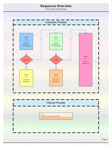
This file is an example showing how the sequence diagram template is used. This file is in .pdf form but is available as a Visio file. Message me through this forum to request a copy. -
View File Sequence Diagram Example This file is an example showing how the sequence diagram template is used. This file is in .pdf form but is available as a Visio file. Message me through this forum to request a copy. Submitter pop29684 Submitted 09/07/16 Category Tutorials and Guides
-
Version 1.0.0
87 downloads
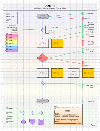
This is a simple sequence diagram format I have developed and used. You may or may not find it to be helpful. This file is in .pdf format but if you message me through this forum I can send you the Visio file. I am offering the Visio file without charge, and without copyright restriction. -
View File Simple Sequence Diagram This is a simple sequence diagram format I have developed and used. You may or may not find it to be helpful. This file is in .pdf format but if you message me through this forum I can send you the Visio file. I am offering the Visio file without charge, and without copyright restriction. Submitter pop29684 Submitted 09/07/16 Category Tutorials and Guides
-
does anyone can help how to connect plc fx2n-16mt with servo drive mr-j2s-40 and motor servo hc-kfs-43 ? please give me wiring schematic thanks a lot
-
 panelview550 error 31 and also not communicating with rslinx and panelbuilder32.whats the pinout diagram of pv550 to rslinx and communication process.i apologize for my bad english beacuse its not my native language.
 -
Hello Dear friends, I have following two problems in RSLogix 5000. I just started working with this software. I am using RSLogix 5000 for my project and I want to use inbuilt drag and drop elements like measuring instruments for example Voltmeter etc. in my ladder diagram. Does it possible or do I need to add some libraries or add ons for that? I want to plot graph of different properties with respect to time in RSLogix 5000. my question is again the same; what is the way to do it or do I need extra Add ons? Thank you in advance for your help :) Merry Christmas!!