
Search the Community
Showing results for tags 'modbus rtu communication'.
Found 413 results
-

Problem with reading Modbus registers In Vijeo Citect SCADA
pateldhavalsm posted a topic in Modicon / Telemecanique / Schneider Electric
Hello there. I have connected wireless module (master) to Vijeo Citect 7.4 using RS-485 to USB converter. My slave modules are supplied power from gird/generator and the master module is supplies from a UPS. I'm reading Modbus registers of slaves modules data via wireless master. Every time we have a power failure from grid, I get #BAD from all slave addresses. The generator kicks off within 30 sec. That is the slaves are off for 30 sec. Even after the slaves are powered on, SCADA does not poll data from it until I restart the SCADA. My current MODBUS parameters are: Inittype = 3, TimeOut = 3000, WatchTime = 10, Retry = 2. Could you please assist me on which parameters to change in .ini so that SCADA reads Modbus registers of slave for more than 30 sec. I tried increasing TimeOut to 30000 but it couldn't solve the problem. I would appreciate if some one could help me out. Thanak you in advance. -
How to establish communication and TIA Portal PLC to detect the PLC within the network that we have defined in the project and thus be able to transfer the program to the CPU detected within this Profinet network. Read more... http://www.tecnoplc.com/comunicacion-plc-y-tia-portal-desde-el-proyecto/ Greetings. _________________________________________ PLC programming and HMI http://www.tecnoplc.com
-

CJ2 to V680S (ETN version) using Socket Service function blocks
Michael Walsh posted a file in PLC Sample Code
-
Here is a recent post that I would like to share. Using Visual Basic 2015 we will log three holding registers from the PLC along with time and date into a Microsoft Access Database. We will log every minute into the database with the information that we collect from the PLC via Modbus TCP (Ethernet). All code will be done and shown so you can implement this in your application with different parameters. The information collected in the database can then be distributed or analyzed in the future. Visual Basic 2015 will be used with the EasyModbusTCP client/server library for .net. We will communicate to an Automation Direct – Do-More PLC. Using the free simulation software of the PLC Designer Software, we will retrieve three values of the Modbus Holding Registers using Modbus TCP. Once we have this information out of the programmable logic controller it will be placed in a Microsoft Access (2010) Database. This will be done by using a SQL command to insert the data. Read the rest of the post... Let me know what you think, Thank you Garry http://accautomation.ca/
-
Hi all, Its the first time in this forum and need help about slc05/05 processor and modbus RS485. We need to link one slc05/05 with 5 power analysers and 3 vfd all with rs485 modbus rtu ports, as i now the slc05/05 have RS232 that suports Modbus, can we put an converter RS232 to RS485 and put slc05/05 to read write the power analyser's and vfd's. There are any sample / step by step tuturial with modbus and slc05/05 ? Best regards, Jorge Cruz
-
I am new to ifix, I am having an issue, I am unable to receive any information, after attempting to fix the fact that the view was only pulling half the data I lost it all, I had a back up saved, but it didn't work on restoring communication, I was getting a cannot connect to node error, but I have fixed that, now all I am getting is question marks. essentially I believe that I have two standalone computers with the ifix software and the communicate directly with various plcs that share information across, either a ring topology or full connected. so the computer I have that is working is setup with scada and the database and MB1 with no network support, the one that is not working is set up the same, my cable connection is a usb to Ethernet and im communicating with a Comm port on the computer. I've tried different comm ports, even contacted GE, they were suppose to have someone call me back but no one has yet. Can anyone give me an idea of what I've got wrong here?
-
Communication issues with PanelView C600 and MicroLogix 1400
python01 posted a topic in Allen Bradley / Rockwell Automation
I am working on a project with Micrologix 1400 and PanelView C600 I am not able to communicate over Ethernet with any device and my computer. I was not able to load the HMI screens so I don't know if they are communicating between themselves. The RSLinx does not see any device connected via Ethernet. I am using EtherNet/IP driver for this, not sure if that is right. I have tried connecting directly to each device from PC over ethernet and also connecting to them through switch. I can however ping each device and the packets are coming back. The IP assignments are as follows: 192.168.0.1 Router 192.168.0.2 PLC 192.168.0.3 HMI 192.168.0.25 PC Would anyone have any suggestions what I need to try to get this resolved? I was able to communicate with the MicroLogix via serial port but was not able to communicate with the PanelView through serial port at all. I have tried using the USB-2711-NC13 cable for the PanelView connection. Thank you. -
Hello everyone, so I noticed in Omron's CP1E manual, there are no certain info on maximum number of Modbus Slaves that can be attached, however the PLC itself able to connect to slave number 1 - 247 I have read from common MODBUS specs, that 32 slaves are the limit for most MODBUS connections. However there are also statements that with proper design (1/8 transceivers) that we can extend number of connected slaves to 256. Anyone have experience or info about this with Omron PLC? Thanks in advance
-
i have this code in c# in order to communicate to cj2m using etheret cable , but i get a connection error ( u can't reach : 192.168.250.1 :9600 ) is there any configuration that need to be done on the plc ? i mean i don't quite get (the node and all thoese properties i fnd on cx-programmer) ?
-
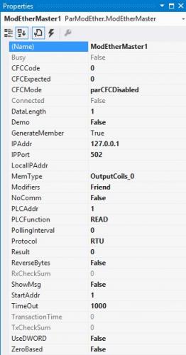
PAROCK1 for HMI/SCADA View File Now a software solution is available for your Modbus (MB) needs in Rockwell/Allen-Bradley Control Logix or Compact Logix (Clgx) family processors, instead of a traditional 3rd party hardware like Prosoft MVI-56, Molex SST-SR4-CLX-RLL etc. It is an Add-on instruction (AOI) for PLC/PAC firmware v16 or later, (other solutions are available for pre v16 systems). For hardware interface, use PLC’s channel 0 (serial) or TCP/IP Interface module(s) to have as many MB TCP/IP devices or serial devices. (Some limits apply based on system configurations, Comm. settings depending on HW used.) Connect any MB Client/Master or Server/Slave device(s) to your CLgx PLC, including flow computers, analyzers, VFDs, Power Monitors, Level gauges, Smart I/O, etc. All the MB public/native function codes are supported. 32-Bit integers/floats as single entity are supported with byte and word level swapping. A separate utility automates the data mapping to your PLC logic. Features -Serial Master (BASIC required Option); TCP; Slave; Redundancy; More than 5000 accumulative registers; MB CFC (Custom/Private Function Code) Support; Data mapping too – Between PAROCK1 & your PLC logic; Packaged with Rockwell; TCP/IP Interface Module; Volume Discounts; Annual Support Requirements -Rockwell/AB-CLgx processor with v16 or later. Contact PCI for earlier versions. -If using CPU’s Chan0, you cannot use Chan0 for any other user mode activity. You can use it for non-user mode activities -TCP/IP Interface Modules from Rockwell/AB supported, are: -1756-EN2xx ControlLogix® Ethernet/IP communication modules, firmware revision 5.007 or later -1756-EWEB ControlLogix Ethernet/IP web server module, firmware revision 4.006 or later -1768-EWEB CompactLogix Ethernet/IP web server module, firmware revision 1.002 or later -1769-L30ER, 1769-L30ERM, 1769-L30ER-NSE, 1769-L33ER, 1769-L33ERM, and 1769-L36ERM CompactLogix controllers, firmware revision 20.011 or later -1769-L24ER-QB1B, 1769-L24ER-QBFC1B, 1769-L27ERM-QBFC1B CompactLogix controllers, firmware revision 20.011 or later -1769-L16ER, 1769-L18ER, 1769-L18ERM CompactLogix controllers, firmware revision 20.011 or later Other Related Services/Items -Custom PLC Add-on instructions building -PLC upgrades, troubleshooting, applications -PC Windows, iOS5, Linux, Mobile devices Comm. Drivers -Custom development, Technology Transfer Services -Other Non-AB communication drivers for serial or TCP -Full control system integration, training, architecture design This driver can be conviniently used with Visual Studio in development of complete large scale complex HMI/SCADA Systems. It can be used to perform advanced reporting MES, analytics, IoT, Big data type apps. One example is available to download here For More Info Overview of Parijat Drivers: Click here Additional supporting Info about Parijat Drivers:Click here Complete Related Driver options: Click here Submitter Scadadoctor Submitted 03/10/16 Category Other PLC Demo Software
-
Version 1.0.0
69 downloads
Overview: The Modbus Master or Client provides an easy and reliable way to connect Modbus Ethernet or serial Protocol Compliant devices with applications, including HMI, SCADA, Historian, MES, ERP and countless custom applications. This driver supports all Schneider Electric (modicon) PLC’s and all other devices which use Modbus as a protocol. Open to support future models for this series of PLCs. Features Modbus/TCP Client or serial Master for communication with Modbus Slaves (Via standard PC serial ports, USB adapters; RTU and ASCII encapsulation in TCP/IP as well as Modbus TCP) Supports all Schneider Electric (Modicon) PLC’s or any other device which use any flavor of Modbus. Supports DANIELS/ENRON Modbus extensions. Can read up to 128 Words of Input / Holding registers or 2000 Bits of Discrete Coils / Input coils in one transaction. Performance –500mhz Pentium–10 words: 15msecs–100 words: 35msecs (avg) Full implementation of Class 0 and Class 1 Modbus functions as well as a subset of the most commonly used Class 2 functions This driver can be conviniently used with Visual Studio in development of complete large scale complex HMI/SCADA Systems. It can be used to perform advanced reporting MES, analytics, IoT, Big data type apps. One example is available to download here For More Info Overview of Parijat Drivers: Click here Additional supporting Info about Parijat Drivers: Click here Complete Related Driver options: Click here -
Hi i am trying to connect to omron plc (cj2m ) using modbus tcp/ip , by using the port 502 i get an error saying that the port can't be reached is there any method to fix that or change the port number ? thank you
-
Version 3.11.2.0
426 downloads
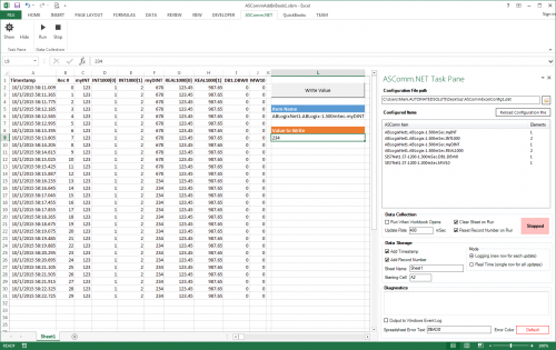
ASComm Excel Add-in is a simple to use, non-programmatic way to populate Excel 2007 - 2021 (version 16) spreadsheets with data from PLCs, instrumentation, and other process hardware. ASComm Excel Add-in uses built-in drivers for Modbus/TCP and Modbus RTU/ASCII communications. No OPC, DDE, external drivers, or programming required -

[Demo Software] - Excel Add-in for Modbus/TCP Data Logging
Automated Solutions posted a topic in Download Comments
View File Excel Add-in for Modbus/TCP Data Logging 3.6.8 ASComm Excel Add-in is a simple to use, non-programmatic way to populate Excel 2007 - 2016 spreadsheets with data from PLCs, instrumentation, and other process hardware. ASComm Excel Add-in uses built-in drivers for Modbus/TCP and Modbus RTU/ASCII communications. No OPC, DDE, external drivers, or programming required Submitter Automated Solutions Submitted 03/01/16 Category Demo Software -
I have restored a crashed IFIX to a new PC. The restore is ok and installed GE9 driver. With the GE9 power tools, we can observed that data transmits and recieve. The problem is that the screen scada is not updating i.e. no status/feedback, anything is happening. The LAN network TCP/IP was configured i.e. IP, subnet and gateway. Any remedies/advice is most welcome. Please provide a guide on the communication/configuration setup. Thanks
-
Hi i am trying to connect to omron plc (cj2m ) from my pc using modbus tcp/ip in c# , by using the port 502 i get an error saying that the port can't be reached is there any method to fix that or change the port number ? thank you
-
How to Send integer files from a panelview component to a modbus TCP Enet device
Steve Ellis posted a topic in Allen Bradley / Rockwell Automation
Hello, I am new to the connected components workbench software. I am working with an AB panelview component Hmi and would like to create numeric buttons to load integers into user variables in a schnieder LMD servo motor. The motor uses Modbus TCP to communicate. It appears that if I click on the numeric buttons properties there is a "Write Tag" of which you can use some default tags or create a new one. I am assuming that I need to create a new one with the motor's addressing but I'm not quite sure how to accomplish this. Any help would be much appreciated!!! Thanks, Steve -
Dear experts, i'm in learning curve to understanding converting DI to Ascii code. i'm attach here my solution that i'm think should be no problem. may i'm know how to send special symbol plc to printer. communication using modbus TCP. Printer format was: JDU |HEAD1|HEAD2|HEAD3|HEAD4| <CR>
-
Hello All, I just had a brain storm while I was setting up a new piece of equipment. As most of us who setup new equipment, we use a long, long, long Ethernet cable when we are trying to reach the end of the machine. I was wondering if anyone has used a portable wireless router instead of a cable. I carry a Cisco router currently, but it isn't very portable. I also thought about Bluetooth, but not sure the range and/or if it works. Any thoughts on products? The big key is portability for me.
-
Hi all. Long time reader, first time poster. I am tasked to make a couple of module specific function blocks for communication between our Mitsubishi PLC (GX IEC Developer 7.04) and a B&R remote IO over Profibus. A number of these blocks would then be used, depending on the RIO setup. Reading should be straight forward, just read X amount of words, starting from address Y. Writing is trickier as Mitsubishi prefers 16/32 bit Data whereas B&R batches Data in bytes! As I have several output modules in the RIO. I need to send my info "chained" together. Example: Module 1: 2 Bytes Module 2: 3 Bytes Module 3: 2 Bytes Totals: 7 bytes or 4 words. Sending the first word is no problem. Neither is the next two words (I will just have 1 empty byte at the end of the third word). But then the info to the third module should start in the middle of the third word. Any idea how I could solve this? Experimental: At the moment the blocks have inputs (bits), which are stored to a bit-array inside the block and then linked to an output. My idea at the moment is to merge all module-wise output bit arrays to one big bit array, converting that to INT and sending it off to the Profibus address. But I have not yet found a way to merge the arrays and shift them so all data is where it should be. Above example: ARRAY [0..15] OF BOOL + ARRAY [0..23] OF BOOL + ARRAY [0..15] OF BOOL Totals: ARRAY [0..63] OF BOOL or [0..71] counting the spare byte. Converted to 8 Words and forwarded through Profibus. Thank you in advance.
-
Hi There i have heard from our local mitsubishi dealer, that there is a Fx3U-ENET module which also supports Modbus TCP. so i ordered one, because i am planning to do a Project using a atv71 FU and a Codesys PLC, so the plan is, that these 3 Devices are able to communicate together over Modbus. has anyone done something similar before? what do i need to setup in FX-Configurator EN, and how can i send modbus commands through that module. i am using GX-Works 2 and have a Structured project. any help would be appreciated. thank you jason
-
Hello everybody, I want make communication PLC FX5U series and HMI GS2107-WTBD. IP for PLC is 192.168.3.250 IP for HMI is 192.168.3.18 I can make upload programs via Ethernet. My Laptop , PLC and HMI are connected toghether via switch. But I could connect data between PLC and HMI. So what must name of device and how to set BIT for example, which must communicate PLC<---->HMI. (bit.jpg) In GT Designer communication also write that i couldn't connect HMI via PLC in red , you can see attached picture. (GS.jpg) smiles : Altan ------------------------ Solved. My error was that PLC and HMI must have different Station Number Special thanks to Piotr Tynor(Mitsubishi, Poland ) , Adam Syrek (Mitsubish, Poland ) , I. Ayvazova (Bulgaria) , K. Raykov (Bulgaria) /you can see atched .pdf file/ MTS0026 - FX5U and GOT2000 (1).pdf
-
hai, im newbie in PLC, anyone can help me to connect PLC LS, expansion XBL c41a to servo L7S through modbus protocol? thanx and best regard
-
Hello, I have the following problem, I have two PLCs FX3U-16M, with a communication module FX3U-ENET-Port502 in both PLCs have built a server under Modbus TCP and a client to read the registers of the other PLC, my code of Modbus TCP client presents the error code C017 and errors in the channels for reading and writing the registers. Of course grateful for his help.
-
I need some help and advice communicating between an Omron PLC and a Keyence KV-5500. My system typically uses an Omron CJ2M-CPU34 which comes equipped with the built in Ethernet IP port. My customer is insisting that we change the CPU in our system to a CJ2H-CPU66-EIP in order to communicate with the Keyence KV-5500. They have not been able to detail why their communications require the CJ2H, they just say they will be using Ethernet TAG communication and for this they need us to change the CPU. Has anyone successfully established communicated between the Omron PLCs and the Keyence? If so how did you do it and which CPU did you use? Is there an .eds file available for the Keyence CPU? Please help!!! They will be visiting from halfway around the globe to test communications in January so I want to be prepared!


