Search the Community
Showing results for tags 'analog rslogix5000'.
Found 133 results
-
Good day everyone, I know am quite new in this forum, but... Please has anyone here actually worked with the analog module FX2N-4AD of Mitsubishi? I have one here with me that I intend to use in controlling a process that will be requiring 4-20mA. Unfortunately, unlike S7-300 or SLC 500, that is quite straight forward, this has been messing with my head since morning. And oh, by the way, am using Version 8 of GX-developer. Any idea on how to go about navigating this mysterious island will be verily appreciated. Thanks. Francis
-
From what I can tell, there is no built-in PLC simulator within RS Logix 5000, and I have to download a separate package that requires another licence to be paid for? Is that really the case??
-

How to use analog values in SoMachine Basic?
mgn posted a topic in Modicon / Telemecanique / Schneider Electric
I'm using TM221CE40T PLC with TM3DI16 DI extension. I'm programming it using SoMachine Basic. In the program I implemented a counter (%C0). I've read in the documentation that %Ci.V stores the current count value. I want that to display this value on a Magelis HMIS5T. How could I store the current count value (%Ci.V)? Thanks in advance! -
hey! I'm pretty new to PLC's, and I'm supposed to ''teach'' the people at my internship how this PLC works, but I have encountered a problem. I've gotten pretty far with all the digital programming and understanding how everything works, but I just can't figure out how the analog inputs/outputs and programming works...... I've had a fair explaination on PID and how this works. I've searched the web as well to figure out what PLC instructions to use. I hope you can answer my following questions. 1, what are the most used PLC instruction blocks which I can use for temperature control, and how am I supposed to use them? 2, Could you please give me an example on how to use PID and what numbers will I need for the calculations? 3, what are the most used PLC Instruction blocks (apart form the analog ones) that I should include in my tutorial? this is my setup: Ethernet switch MOXA EDS-205 Plc voeding PA202 PLC CPU CJ1MCPU11-ETN Digital IN (16x) CJ1W-ID211 (SL) Digital IN (16x) CJ1W-ID211 (SL) Analog IN (8x) CJ1W-AD081 (SL) Analog IN (8x) CJ1W-AD081 (SL) TRANS OUT (16x) CJ1W-OD212 (SL) TRANS OUT (16x) CJ1W-OD212 (SL) Analog OUT (4x) CJ1W-DA041 (SL) thank you soo much for looking at my question and considering helping me! the OMRON helpdesk hasn't been very helpfull. kind regards, Deuslupos,
-
Good day, I'm new to this forum and to mitsubishi PLC but was hoping for some assistance with a programming issue. I have been through the hardware and programming manuals without luck for this issue. Hardware: FX3G-60mt FX3G-2AD-BE Settings: Structured ladder/FBD Current input mode on: M8260 (first board, first input) What I need to do is to record the peak value over a cylinder stroke period. The hardware manual explains how to average the value using averaging time, however I basically need to peak hold and send that to a D register for go no-go compare. Process as follows: Contact closed, monitor D8260, contact open, move peak value from D8260 during monitor duration to D205. Thanks in advance for any assistance. -Swervomotor
-
Delta DVP-10SX How to read analog value and display it at the built in 7 segment display
RothmanDaLuck posted a topic in Other PLCs
Hello, does anyone here know what instruction to use to read the analog value from ch0 and display the reading for DVP-10SX plc? I'm lost, need help. -
Hello Experts I am facing problem with CJ Series Analog I/O module MAD32. The Run LED is Lit, ERC Led is also Lit. what could be the reason?
-
How do I add a constant string to a CompactLogix PLC and RSLogix5000? How do I copy one string to another? I have found links to using the COP instruction, which is fair enough, but the source parameter needs a tag and not a literal. How do I get a value into the tag? Can I really only do it when online? I'm new to Allen Bradley, and finding string usage to be very confusing so far.
-
Siemens S5 to Controllogix conversion
Falcons75 posted a topic in Allen Bradley / Rockwell Automation
I'm in the process of converting an old Siemens S5 project (with no comments!) to ControlLogix. My first question is in the S5 there is the odd instruction with a '#' in it: - -] [ - - - - (#) - - - - ] [ - - - - -(F00.1) In old logix the # means a file, what does it mean in Siemens speak? My next question, I have the rockwell document for structured text and also for converting S5 to logx, is there any other resource that would help me understand Siemens structured text? As I chip away at the project I'll be posting more questions. Thanks in advance for your help. -
Schneider Electric TMC2AI2 analog input
Randy765432 posted a topic in Modicon / Telemecanique / Schneider Electric
Having problems with the analog drifting. Over time the counts change. I have checked grounding and have tied the analog common to the DC common which helped clean up the noise. I am using a Balluff analog linear sensor 0 - 10vdc for the iputs. Both channels seems to drift. Any Thoughts? -
Version 1.0.0
406 downloads
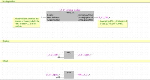
This is just an example how to convert an analog signal (0-10V) Library used: AnalogFX_V310 -
[PLC Sample Code] - FX0N analoge module, scaling and offset.
HwT posted a topic in Download Comments
View File FX0N analoge module, scaling and offset. This is just an example how to convert an analog signal (0-10V) Library used: AnalogFX_V310 Submitter HwT Submitted 03/13/16 Category PLC Sample Code -
Greetings, I've been having some issues with a vacuum pump breaker tripping... I think I've figured out the problem and resolved it but I noticed that several of the other motors have current monitoring on the HMI but the person who set this up is no longer with us. I'm wondering what I need besides an analog input for my control logix processor (which I have) to setup this project. I'm not sure if the other motors are just monitoring one leg of the 3 phases or if they are somehow showing total current? any ideas and recommendations would be greatly appreciated. thanks,
-
Im working on a way to reset a RTO (retentative timer) that counts how long a motor runs above alarm current levels and keeps a record of the highest current recorded... currently it just counts forever but I want to reset it each month... and to possibly move data into monthly registers to evaluate and compare. I have my GSV setup monitoring the clock and am trying to think of a way to monitor my WALLCLOCK[1] DINT that houses the month (Currently 2) I want to trigger a reset anytime that DINT changes state.... any ideas??
-
AB analog input card response time too slow compactlogic
leescott posted a topic in Allen Bradley / Rockwell Automation
First post. We recently upgraded our machine from an SLC to compactlogix. In the SLC 5/05 we used analog 1746-ni8 cards for pressure and position sensors. When we moved over to the compactlogix 1769 l36erm with 1769-if16c cards we seen issues where the analog values had very little definition accuracy. This can be resolved by changing the filters but then the response time of the card is to slow and we miss data. All of the relevant code from these sensors are in their own task and ive tried periodic, event and continous tasks but none of this helps. The strange thing is with the SLC we never seen these issues. Any ideas how i can improve the reponse time when the filters are set low? -
How to correct Analog I/O config problems in PLC5
rdarling3599 posted a topic in Allen Bradley / Rockwell Automation
Have a PLC5 project with remote racks with digital and analog I/O. For test purposes have wired AO to AI and have set up the BTW and BTRs. Problem is I put a value in the N11 register for the particular AO (N11:66 - BTW) and it doesn't appear in the other N11 register for the particular AI it is wired to (N11:4 - BTR). The AI - N11:4 continues to read a value of "8259" in decimal/"2042" in BCD, despite any value I put in the AO N11 register. The range of the AO is 4-20 mA with a Raw min of -4095 and a Raw max of 4095 and the range of the corresponding AI is 1-5VDC/4-20 mA. If I remove the wiring arm of the AI, the N11 register will read "4135" decimal. Would appreciate any fdbk as need to get working as system for customer will not be migrated to newer RA or Siemens system til next year. Cant get support out of AB for questions as only have standard "tech connect" tech support contract and PLC5 requires you to have "Legacy automation" tech support added to your "tech connect" stnd contract. -

IN NEED OF RSLOGIX 5000 SAMPLE CODE
electric101 posted a topic in Allen Bradley / Rockwell Automation
Greetings, I'm ok with RSLOGX 500 but am an absolute beginer with RSLOGIX 5000 and was wondering if anyone had any simple sample code just to study. I would love something using analog input and or analog output. thanks in advance. -
Hello. I searched for an answer for this but it is still not very clear to me. I have a new Guardlogix 1756-L72S. I would like to create a project to work with it with firmware version 20.13. I have RSlogix5000 v20.01(CPR 9 SR 5) which should be compatible with it (in fact I can open projects with another guardlogix that have that firmware version) BUT when I create my new porject, the firmware version RSLogix5000 puts is v20.11 1. How could I create a project with the firmware version 20.13 for my guardlogix? (Didn't find an AOP for this) 2. If I update the guardlogix to firmware 20.13 with the CONTROLFLASH, could I still be able to go online and work with it, even though my project has a different firmware version? Thanks!
-

Progressive user libraries for signal processing of FX-series analog modules
Inntele posted a topic in Mitsubishi
https://plus.google.com/u/0/collection/oCtiX To be continued... -

CompactLogix using Analog Press Encoder
jrupp82 posted a topic in Allen Bradley / Rockwell Automation
I'll set the scene a little before I explain the issue that I am having. I have an application where I have a Linear Servo Slide acting as a Press Kick-off cylinder on a ceramic press. In order to trigger this Slide accurately, I have installed an Absolute Rotary Encoder (a Turck product) to the press, which outputs an Analog signal for its specific position. I then have this as an input into my CompactLogix L33ERM through a 1769-IF4 Analog Input card. Within my code, I'm trying to capture the moment where the press has presented the part out of the die and it can be ejected from the press cavity without damage the part. Mis-timing on this ejection and the part will clip the die pad tooling and incur damage upon ejection. Now, one last point of clarification, I am a Mechanical Engineer by trade, so I don't claim to be an expert programmer. But I have learned a lot and have gained experience in programming applications like this, so I can learn quick and should be able to program this task. I have had my local Allen Bradley guy look at the code I'm using for this application, and he thinks it looks good, but I'm still having issues. What I have done, is within the code, I have a window that I look for, of the encoder's position, to trigger the ejection shoe to fire its sequence and kick the part off. However, I have had to make this window so large in order for the code to see it every press cycle, that occasionally, the ejection shoe will be fired at the back end of the window, which is actually too late, and my part is being damaged. Attached is a snapshot of the code. The OkSamplePress.DN is actually a timer that I have that looks at the current press rate and puts a delay in to not allow the kick-off to fire too early, because I was actually getting a glitch before where the kick-off would fire prematurely for some reason. I don't know if anyone can offer assistance on this or not, but I would greatly appreciate any help at all. Its become quite frustrating, as the rest of my machine functions quite well, and this seems to be the nagging issue I can't get rid of. Thanks in advance...Josh -
I've got a PLC stack with a Q64AD analog-digital converter card. I am attempting to read the digital output value of channel 1 but I am having issues. First of all here is my simple PLC program: I got the program from the Q64AD user manual. You can see there is a blue '0' on the right of line 0. I assume this is the value that is being read? When I monitor the D11 device in GX Developer it shows a '0'. The following is a screen from Online > Monitor > Buffer memory batch. My card has a base address of 0x60 and channel 1's offset is 11d (0Bh). The value on the highlighted line does change so I know that the analog card is correctly picking up on current changes from my source. Lastly here is an image of my digital inputs. I have set up the Q64AD card through the GX Developer PLC Parameter window and left all settings as default. I initially used 'K11' instead of 'H0B'. I have also tried using the MOV command (MOV U0\G61 D11) but that game me the same result. Can anyone spot the flaw in my program of configuration? Do I need to configure the PLC in order to use the 'D' devices? Should I try copying the value somewhere other than D11? Thanks
-
CONTROLLOGIX 1756-L61S DO NOT HAVE PASSWORD - IS THERE A FIX?
sappleto posted a topic in Allen Bradley / Rockwell Automation
Several years ago before I arrived at my company, an integrator came in to do the automation on our system. They used a Controllogix 1756-L61S for the safety portion of the project. Apparently, when they completed the job they did not provide the source code with comments, safety password, etc. for anything and it got ugly between our company and theirs. In other words, they would not provide it if we went back to ask them. Allen Bradley has told us that we can not make any alterations now to the safety logic because we do not have the password that was used to create it. And they said there is no longer a master password that you could use like in previous controllers. Does anybody know of any workarounds for this? Or have heard of anything that might possibly work? -
Hi, I am looking for a Modbus TCP based AI and DO data acquisition module and scada program. The analog inputs are 4-20 mA . SCADA should be able to communicate over Modbus TCP( I think every SCADA does that but just want to make sure). Can you guys please suggest if you know something good fit my application? Thank you,
-
I am installing a new device that is really easy to set up with an add on profile (AOP). However, the PLC I am using is only a version 13.44, and I need it to be at least version 15 to use the AOP. Is there a way I can upgrade the PLC to a newer version so I can use the AOP?
-
Download mode bit in RSLogix5000 CompactLogix?
hboyer90 posted a topic in Allen Bradley / Rockwell Automation
Hey, this may be an obvious question, but here goes: I have a CompactLogix L36ERM running RL5000 controlling one of our lead die cast machines. When I make a change to the program offline and need to download I always go and shut the machine down for safety reasons before downloading. One of our techs stopped the machine but left the control power and hydraulic pump on while downloading (something we are not supposed to do) when he finished downloading he switched it back to run mode and the machine closed on it's own and started right back up. This is a safety concern to me. We have a "close enable" tag that is true when all necessary conditions are met, and gets latched on when the machine is running in full auto. Before he downloaded the machine was at idle, meaning that the only way to close the machine would be to press the two dead-man switches to start the process. But, when he downloaded it started up automatically. Now I know the reason why is when the program was last saved, the "close enable" tag had a value of 1, it was latched on, so it bypassed the dead-man switches. A quick fix would be to save the program with that tag un-latched so that it can't start up on it's own after downloading. But, in case somebody saves the program while the machine is running and with that tag latched on, I need a better solution. Is there any tag or bit that goes true when a program is downloaded or when the mode of the PLC is switched from run to download to run? I want to manipulate that tag so that when I download it un-latches the "close enable" tag. I'm sure there is a way to do it, I'm just not even really sure what to search for in the online help. Any help is greatly appreciated. Thanks Howard