Search the Community
Showing results for tags 'address register range'.
Found 54 results
-
I am working on resolving issue in Press Machine where previous engineer has developed logic as per attached file. the atatched screen of HMI can only access by Engineer and only Engineer can set value of SPM (Stroke per minute). Once switch is set on the SPM of any job can not go beyond set value. The issue I am facing it when we power cycle, the switch get off and the register D2842 get SPM back to normal (set as per the die data) not by eng. How I can hold that data after Cycle power?
-
Hi all, I am working on a safety PLC conversion project, for which I need to identify the input word address configured on a PSS AI IP card. The manual from the official website shows the address configuration via a DOS tool. I do have PSS SW PG WIN 4.9, but the project file has been created with PSS WinPro 2.3. Within this software there is only the option to configure how the input channel behaves, not which input word is used (see attached screen grab). Anyone with a distant memory if the addresses can be set with PSS WinPro?
-
Hallo my name is Danu, i have a CP1E wirh CP1W-CIF11 and connect to modbus RTU device, i have done with write single coil, write single register, read single register and read multiple register. But i try to write multiple register, the indicator of CP1W-CIF11 is off and if i check d memory its no data. I attached my cx programmer. Can you help me create write multiple register in cx programmer? Thank you AD4402-modbus edit edit edit edit edit.cxp
-
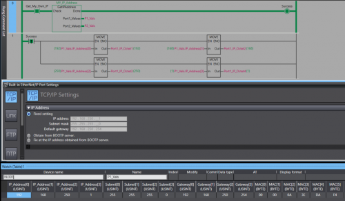
View File NJ/NX Get IP Address A Library containing a function Block that can be run on any Omron NJ or NX PLC. The Function Block will retrieve the host PLC's IP address, Subnet Mask, Gateway, and MAC Address. The Port Details are presented through 2 structures , 1 per-port. In the event the PLC only has one port the structure for Port 2 will be blank. Submitter photovoltaic Submitted 12/12/22 Category PLC Sample Code
-
Version 1.0.0
76 downloads
A Library containing a function Block that can be run on any Omron NJ or NX PLC. The Function Block will retrieve the host PLC's IP address, Subnet Mask, Gateway, and MAC Address. The Port Details are displayed through 2 structures , 1 per-port. In the event you only have 1 Ethernet port then the structure for the 2nd port will contain all 0s. Data Format: IP Address - USINT[4] Subnet - USINT[4] Gateway - USINT[4] MAC - BYTE[6] (hex value) Access the retrieved details by the typical parent-child tag structure. ex. Port_1_Detals.IP_Address[0] will get the first octet of Port 1's IP. Tested on: NX1P2, NX102, NX502, NX7, and NJ301 IMPORTANT: This Function Block should not be run immediately after startup. Allow the PLC a few seconds to establish a connection with the Ethernet network. -
Is there an efficient tool to manage and validate CX-Programmer addressing. Requirements: - Highlight Duplicate Address allocation - Compact/Defrag address range to avoid wasting memory space. Note: - Any FINS addressing will have to be reconfigured - This approach assumes symbol use rather than direct addressing in the logic.
-
Array A INT[32] Array Index B INT Destination C INT I am trying to move an Array (A) Element (A[2]) using a symbol (B) in ladder into a destination symbol (C) C = A [ B ] Result: ERROR: Array Index of Operand 1 out of range at rung 1 ( 6, 0 ). The documentation suggests that it is possible, but I am unsure if there is something I am doing incorrectly. Note* Fixed indexing works with no errors Is there another method to accomplish this? PLC : CJ2M CPU31 CX- Programmer: Verion 9.74 Update 1: If I go online to the PLC It does look like the array look up is working. Is the issue with the mov block? Update 2: I changed the memory locations which has caused a different error to appear. This error is clearer but does not explain the manual excerpt I posted further up ERROR: Only the constant can be specified for the index of the array. at rung 5 ( 6, 0 ). Update 3: Solution 1 I managed to hack together a proof of concept using pointers and indirect offsets Update 4: Solution 2 For some strange reason things work as expected inside of the function blocks so I made one where the array is In-Out and with an input and output respectively. Note* External reference to pointers inside of the function block produced an error. Function block Logic Update 5: Solution 3 Now I feel like I am going crazy, I tried just the original code again and it works... I have no idea why and if it was not for all the documentation I would be lost as to why it works now... Update 6: Conclusion It seems to have array indexing work the array index must exist in the D Memory Block. The reason it did not work above is because I somehow had a MOVR block when I tested after moving all the variables to the D Memory Block. I hope this journey helps someone else :)
-

there is a device in the program (main) that is outside of the range
techsupoortalpha posted a topic in Mitsubishi
Hello, Good Day All. I am facing this issue while I am going to copy old plc to new plc. but old plc having 4965 steps, once going execute this program to new plc its showing more than 8000 steps. please suggest on this. PFA. -
It will de nice to have an option for getting a cross-reference report for the AT address used on programs , as is now its easy to make mistakes double setting the same AT address on a program , specially this days that supplies of NA screens are not always availiable and using memory address is necessary for NB screens and SCADA communication and is difficult to keep track of the used address on a program , some times in global or in internals, right now its easy to make a mistake and use the same address twice , and this wont be detected on the compiling
-
Hello to everyone. I hope you are doing well. I have a KINCO PLC HP043-20DT. I'm communicating through free-protocol instructions XMT and RCV. The manual states that memory registers SMB86, SMB186 and SMB286 contain information about the state of the reception instruction. I would like to ask if any of you know of the existence of an analog register but with respect to the transmission instruction, instead of the reception. The manual does not indicate it and I could not find any information online. I've sended an email to the manufacturer but, until now, I have not receive any answer. Otherwise, how could I search for this information? I tried through the manual providede by the manufacturer, but maybe there is other way. I would appreciate any information. Thank you so much. Kind regards.
-

Zebra Industrial Printer and Allen bradley L18ER printing via Ethernet IP
AniAutomationIndia posted a topic in Allen Bradley / Rockwell Automation
Mail me for Help if anyone is stuck during coding and settings. -
i want to use indirect register, but why contact 100,IR0 is not ON, is it my program correct?
-
Hi I'm trying to set up Modbus RTU communication between FX3U PLC and a weigh module. I would use the ADPRW command using 0X03 to read the 16 bit Holding Register but in the weigh module the Data Address/Holding Register of the value I want to get is 400047 - 400048. How to translate the value in 16 bit? Thanks, Fabio
-
I'm writing a PLC program (Q Series Mitsubishi PLC, GXWORKS 2 Software) for a package sorting machine. The logic of the machine is the following: Packages are induced in the conveyor. A barcode reader scanner gets the package barcode. Barcode is send to our SMS (sorting management system), it calcules the exit and send it back to the PLC. Package travels to the calculed exit, then is derived into the chute. The tracking of the products is done by an encoder and a shift register. This means that every memory address represents a physical position in the conveyor. Then, the shift register move the bits representing the packages along the memory buffer, till the bit arrives to an address that represents an exit, so the package can be derived. My problem is not the tracking of the product, but the product ID tracking: When a package enters in the conveyor, an ID is set for that product (1,2,...,n). The idea is that this ID is used to track the state of that package, for example if the package was derived in the correct exit, if it has a damaged barcode, etc. My question is, how can I track this ID along in an efficient way. I was thinking in use the same shift register not moving a sole bit, but moving a larger number for example |1|0000011|, where the first bit acts like a flag that represents the existence of a product and the rest of the numbers is the product ID. When the flag gets to the exit address I can substract 10000011 - 10000000 = 00000011, to get the product ID. Is any more efficient way to do this ?
-
Hello, I have an M2I Top RW (model: 1000WD) connected to a Schneider Modicon M221 PLC. The HMI is connected and I is working perfectly reading data from the PLC via ethernet. I can't seem to find a way to write to the PLC from the HMI. I would like to control the PLC from the HMI, I know this is possible with Fatek PLCs with the same HMI model. please help - how would I create a bit command from the HMI to the PLC? what registers? what inputs in the PLC? thanks
-
Dear Engineerds, My Master (non siemens) doesn't see the Holding Registers of the Slave (S7-1200) plc. However the Q coils are fine and all Diagnostics don't show errors. The Hardware: S7-1200 – CPU 1215C CM PtP – CB1241 RS485 (6ES7 241-1CH30-1XB0) - Half Duplex RS584 Firmware: Modbus_Comm_Load (V3.1) Modbus_Slave (V4.0) I've tried with various DB, UDTs and manipulating HR_Start_offset parameter with no success. Could you advise what am I possibly missing? Modbus_Comm_Load_DB_Snapshot.xlsx Modbus_Slave_DB_Snapshot.xlsx
-
Dear Sir. Can Anyone Help me,How To read Holding Register QM30VT2 BANNER With QJ71C24N Mitsubishi ,With Rs 485 Communication.I Want To read Holding Register it,More than 2500 Register. Thank you for attention. Best Regards.
-
CP1L-L14DRD CP1W-AD041 I have my configuration words set to #80BB for both output words with the intention of having 0-10 input. With my input voltage at 5.25 I get 6300 the maximum range. I entered the bit wise in my calculator 1000000011011101 and it converts to 80DD. Tried both those options with the same result. Can anyone shed some light on what the problem is?
-
I have a 4PP015.0420 panel with the led error that stays between green and red, and it doesn't work.The sequence of the LEDs at power: Yellow Red Green Red Green Green Green Green&RedAnd on the display : Version 1.1 Status 400041000I think there is a Status Register that indicates the errors.How can I see it to know why the PLC is not put in RUN?Thank you in for your help.Sorry for my english
-
hi all, i'm currently trying to shift register some data in the floating point (double word) format, just for an example i,m using a 0-20mA 0-40 bar pressure sensor to gather information from a can filler and want to log the data for lets say the previous 20 cans. i understand how the shift register works and can get it to work with single word just fine, im using floating point to make my life a bit easier by using sleepy wombat's scaling function block, i need decimal points as i will be expecting reading around 4.5 or so bar and expected to be within .2 tolerence this will then have to displayed on a HMI, which i assume will be easy enough
-
Micrologix 1400 recording off time of a DI
Ryandevlin17 posted a topic in Allen Bradley / Rockwell Automation
Hi, I'm pretty new to allen Bradley and wanted to know if there was a function that could help me out. I have a rotation sensor which feeds back to the PLC via a digital input, once every half second or second once machine is up to speed - I want to record the off time of this DI (how long it is off between pulses, essentially how long it takes for drum to rotate once). Is there some way to record this time and use this value for compare logic? any help would be greatly appreciated. PLC: Micrologix 1400 series B RSLogix 500 version 11.00.00 (CPR 9) -
Communicating between plc's with different IP's
plcaholic posted a topic in Allen Bradley / Rockwell Automation
I am trying to get produced and consumed tags set up between 2 1756 racks with different ip's. The 1st rack has an ip address 172.28.6.3. The 2nd rack has an ip address of 10.81.105.8. Would this be as simple as adding an EN2T card to one of the racks and setting the ip of one onto the same network? Or is there a better way to do this? -
Hi guys, I've just completed pre-commissioning on a Mitsubishi project which uses CCLink. My remit was to get the CCLink network up and running which I eventually did but not without issues. Basically, my problem was to do with the number of bits and registers consumed by a station. I read in a manual that each station consumes 32 bits and 4 registers for read and 32 bits and 4 registers for write. On my network I had 3 ST1H-BT modules occupying 2 stations each and 3 non Mitsubishi devices occupying 4 stations apiece. My RWr address starts at W300 and RWw at W500. Like I said everything matched up and I/O checks completed successfully. My question is, and I've trawled through the manuals looking for an answer, how is the number of points calculate? For example my non-Mitsubishi devices they occupy 4 stations, Expanded Cyclic Setting is Octuple and the number of points is 896. How is the 896 calculated? Thanks in advance
-

Is it possible to change the range setting for NX Analog IO cards?
TigerLily posted a topic in NJ Series / Sysmac Studio
I am beginning my first project with the newer NX platform and am a little confused by the description in the manual vs what is actually in the sysmac setup. The manual makes it sound like you can adjust the range settings for the card, but I don't see any where to do it in the setup. I also don't know what the Index and sub-index columns mean, so I am wondering if this is a back door to access the range settings? -
Hi everyone My system consists of 2 main stations with 2 CPU Q06UDEH and connected together by QJ71GP21S-SX module but I don't know how to link the address between these 2 CPU together? so can anyone help me? Thanks so much