Search the Community
Showing results for tags 'logo siemens compact logix network'.
Found 298 results
-
All, I am using Keyence CV-X422A vision controller for my application. It is interfaced with Siemens S7-1500 PLC on PROFINET. I am able to communicate with Vision controller through PLC logic command and status IOs. There is some communication issue in updating the o/p values from Camera Controller. I have tried with & w/o Handshake Mode with these settings. The camera display shows the reject but camera never turns ON the NG Status o/p. I tried different things told by Keyence Tech support but none of them worked. He told me to have you enable the “Result ACK Flag” in the bit allocation area and send a signal to it. Then trigger it again with a no good part and see if that fixes the issue. I tried setting the “Result ACK Flag” to 1 after I get the “Command Complete Flag” for the trigger signal that I sent. Sometimes this works but still it is not reliable. Do I need to send only a pulse to “Result ACK Flag”? Anyone here has ever faced similar issue? Thanks for your help. AP
-

PROFACE HMI AND SIEMENS TRANSMITTER
0608jai1990 posted a topic in Modicon / Telemecanique / Schneider Electric
Greetings everyone, I have a Proface HMI(LT-4201TM Modular type DIO) connected to a siemens flow transmitter(MAG6000). Communication between these two devices is using modbus. The modbus register that im using to get the data/reading of a totalizer from siemens transmitter are 403022 and 403023. I managed to display the exact totalizer value from siemens transmitter on the Proface HMI screen. But I couldnt get the exact totalizer value at the ladder logic side, the value that i get at the ladder logic side seems like a raw value. For an example, the totalizer's value is 147083(real value), but at the ladder logic side the value for 403022=15598 and 403023=17316. Can anyone guide me to solve this issue. Thanks in advance. -
My issue is trying to receive data from a Datalogic PM9500 barcode scanner onto a Siemens ET200S (IM151-8 PN/DP) CPU using a serial interface card (6ES7 131-4BD01-0AB0) with the ASCII Protocol. The software that I'm using to program the PLC is TIA Portal V14. I made use of the built-in function block S_RCV to try and receive the data into a data block that I have created. I connected the Datalogic's base charger unit directly into the PLC's SI module. (I cut the DB9 plug off) So, Pin 5 (RXD) of the SI module is connected to the Tx wire (Brown) of the scanner, the Tx is also connected, as well as the ground, to the SI module, however, I only require the Rx. There is no flow control. Upon scanning a barcode, the Rx LED on the SI card flashes, indicating that something was received. I have tested the scanner using a terminal program called "Hercules", and I am receiving what I should be when I scan something. The parameters such as Parity, Stop Bits, and Baud Rate, etc, of the scanner corresponds to that of the SI module as well. I paramatized the S_RCV block as follows: 1.) EN_R is always ON. 2.) R is defaulted to the instance DB that was created with the function block's tag. 3.) LADDR is set to "100" as that is the start address of my SI Module as defined in the device configuration. 4.) DB_NO is set to "2" as it is the number of the data block I created for storing the received data. 5.) DBB_NO is set to "0", which I understand to be the data blocks offset start point from where to start inputting the data. The rest of the NDR, ERROR, LEN, and STATUS outputs of the function block are also defaulted to the instance DB tags. I only want to see if I'm receiving the data from the barcode scanner into the datablock. I created an array of bytes and I also tried with characters from 0 to 30 to store the data. As I mentioned, the problem comes when I'm trying to scan something, the RX LED on the SI module pulses, but when I monitor for any changes in the Function Block, as well as for any changes in the Datablock itself, nothing happens at all. I don't know what If I'm missing something, this has been bugging me for some time now, I'm quite new to the whole programming scene, I would appreciate any help I could, get also I've attached the project file too. =) Yumi_Panel.zap14
-
Hi, I'm attempting to convert some old Siemens workshop 505 code to control logix and i have basically no siemens experience at all and i'm confused as to how to tell what actual output card X1 or X2085 is referencing?? same with inputs.
-
ello.I am Melani. I working on to convert Siemes S5 code to Logix5000.Following is FB that need to convert.Segment 1Name :John0005 :C DB 2100006 :L FW 400007 :T DW 20008 :L DW 60009 :T DW 1000A M001 :L KB 0000B :O DW 1000C :T FW 0000D :L DW 1000E :L KB 2000F :+F0010 :T DW 10011 :L DW 80012 :<F0013 :JC =M0010014 :L DW 20015 :T FW 400016 :C DB 1500017 :L KB 00018 :T DW 10019 :T DW 2001A :T DW 3001B :***How to convert this code to Logix5000 either structure text or ladder logic?Thank you if anyone can help me to convert it.Thank you.Melani
-
Generic Routine to Decode data for one than one Module
Muhammad Azeem posted a topic in Allen Bradley / Rockwell Automation
Hi, I am writing some routines to decode the data from my Input: data array to User-defined Array Parameters. Is that possible to have a generic routine to decode data coming from more than one module? I have two Module ENode and ENode_1. I have defined User-Defined parameters for the module. Can I make a generic routine to decode the data coming from these two modules and put them in the defined arrays? the two arrays ENodeData[0] and ENodeData[1] have the Generic User-Defined parameters. -
Hi dear friends, i'm working with a Siemens PLC LOGO 8 (OBA8) that connected to a Wientek HMI model MT7081IE via Network. and my Problem: i'm trying to get the PLC LOGO time for displaying and editing on the HMI panel, i know that the Time address in the plc logo8 is VM988 and VM989 and VM990 (Hour:Minute:Second) but in easy boilder when i selected an Numerical object there is only VD and VW variables available to select and there is not VM selection (Please see the attached picture). thats way i select VW pisition with the same position Number (for example VW988) for get the Hour value and it's displays a big binary number that contains Hour and minute value in binary, also i can find that witch characters are for hour value and witch one are for minutes value. Please help me that how can i separates the characters and dispalys them into another numerical objects? or another ways to get time values from the OBA8 and displaying on the HMI. Thanks and Regards Saber
-
Hi, Is that possible to define INT data type in EDS file so the Tags for the module in RS Logix Designer would receive INT data type in Input Tags not SINT? As marked in the image, the Logix Designer is receiving data as SINT but I want to have INT data type. Thanks Muhammad Azeem
-
ARP-ing behaviour of an AB PLC (1756-EN3TR/B v217021900)
MrRobotics posted a topic in Allen Bradley / Rockwell Automation
Hi All, Networking guy here, looking for network experts on a AB PLC (1756-EN3TR/B v217021900) which seems to STOP ARPing for a device after 10 ARP's. The device is purposefully powered down, but when powered up, it can take minutes before the PLC sees it again. The PLC team says only changes in the PLC's logic are made. When an older backup is restored though, I do NOT see the issue somehow. 1) The devices that are powered down are back on the network and reachable within 10 seconds or so (ping). The initial thought was that they were not even on the network, but they are. Just that PLC shows a comms loss. 2) With the 'good code', the PLC, once the device is offine, keeps sending ARPs to find the device. The first one is a directed one, the subsequent ones are broadcasts. These broadcasts keep happening till the device is back online and is able to talk to the PLC again. 1st ARP after comms is lost: 474.423859 Rockwell_cf:a7:6c Hilscher_2e:ea:08 ARP 60 Who has 192.17.150.208? Tell 192.17.150.30 Next and subsequent ARPs after the first one: 475.423471 Rockwell_cf:a7:6c Broadcast ARP 60 Who has 192.17.150.208? Tell 192.17.150.30 These ARPs keep happening every 1 second, till the device is online again. 3) With the bad code, the PLC, once the device is offline, sends only 10 ARP messages total and then stops sending ARPs altogethe . Then it takes 10 minutes* before it sends another one. If the device is backup online by that time, the PLC finds it right away. SO with these 2 different code bases, how is that a low level L2 protocol like ARP is impacted so much. The PLC team tells me that they have no idea and not set anything related to it. My question is where is the ARP network behaviour governed and how to change it? How can older code which supposedly only has changes in logic have different ARP behavior? * The 10 minutes interval might lead people to think it's a ARP timer and most likely it is, but then people usually ask about gratuious ARPS (garp) and I've verified that they make it through from the device to the PLC OK. If the device is offline for say a minute, the PLC mirrored port does indeed see the garps, yet at that point the PLC is no longer ARPing and regardless of that garp, it has to sit out the time till it sends a next ARP till it connects. Thus, I suspect the coming back to life process is governed by the PLC ARPing for it, and not by the detection of a garps. Thanks everyone! -
Programista PLC Automatyk - Kraków / Piła / Poznań
ProfasGrupa posted a topic in For Sale, Employment, Services or Wanted
Grupa ProfAs Sp. z o. o. jest firmą doradczą, świadczącą usługi w szeroko rozumianej dziedzinie Human Resources. Specjalizujemy się w rekrutacjach na stanowiska specjalistyczne, średniego i wyższego szczebla. Wierzymy, że nasz Zespół złożony z profesjonalistów jest w stanie zapewnić perspektywiczne spojrzenie i najwyższą jakość wykonywanych usług. Aktualnie dla naszego Klienta - firmy z branży automatyki przemysłowej - poszukujemy osoby na stanowisko: Programista sterowników PLC Kraków / Piła / Poznań ZAKRES OBOWIĄZKÓW: Programowanie sterowników PLC Siemens Wykonywanie aplikacji dla systemów SCADA i HMI Dobór konfiguracji sprzętowych PLC Testowanie i uruchamianie maszyn u Klientów końcowych (delegacje krajowe i zagraniczne) Wykonywanie programistycznych prac serwisowych u obecnych Klientów Sporządzanie instrukcji obsługi maszyn WYMAGANIA: Bardzo dobra znajomość sterowników PLC Siemens Umiejętność parametryzacji serwonapędów, falowników, etc. Znajomość paneli HMI oraz systemów SCADA Znajomość sprzętowa oraz programowa komunikacyjnych sieci przemysłowych ProfiBus, Profinet, Ethernet, DeviceNet, Modbus, etc. Znajomość zagadnień i komponentów automatyki (przetwornice, serwonapędy, obwody bezpieczeństwa, aparatura modułowa, itp) Mile widziana znajomość programowania innych sterowników: Allen-Bradley, Omron Prawo jazdy kat. B Komunikatywna znajomość języka angielskiego lub niemieckiego OFERUJEMY: Współpracę w oparciu o umowę o pracę Udział w profesjonalnych szkoleniach Korzystne warunki wynagrodzenia Rozwój w firmie z doświadczeniem na rynku międzynarodowym nr w rejestrze 14990 Osoby zainteresowane prosimy o przesyłanie CV na adres k.dominik@profas.com.pl lub kontakt telefoniczny pod nr tel. 881 700 778. -
Micrologix 1400 HSC INPUT PULSE REQUIREMENTS
neech posted a topic in Allen Bradley / Rockwell Automation
I have a "paddle wheel" style flow meter that I am trying to wire to my Micrologix 1400. It is a three wire device and there is a tag on it that says it can run at 6-36VDC. So, naturally, I thought to wire this to one of the HSC inputs of the Micrologix directly. I hooked the ( + ) on the meter to 24V, ( - ) on the meter to common, signal to the oscilloscope, and ground on the scope went to common. I see a small 60Hz sine wave @ like 5mv when the wheel is not turning. When the wheel is turning I get a small square wave but in the same mV range. It is not a nice smooth square wave either its all jumbled up with the 60Hz sine wave. I hooked this thing up to a transmitter and scoped the signal and ( - ) in parallel with the wheel - I get a nice smooth square wave signal when the wheel turns. It is only at 4.5V though. My questions are? Why does't the paddle wheel give me what I am expecting directly? Also, what is the voltage range on the pulse that a micrologix will see? I am assuming that it will not count a wave with a 4.8V amplitude.... Thanks for your help in advanced! neech -
Hello, I need to make an ethernet communication Siemens S7-300 <> Omron G9SP. The HW of the Siemens that i us are CPU 315 2DP and CP 343-1 Lean. I did try to follow the Omron manuals Z922 and Z924, but faced with some problems. First of all in Z924 there is no complete HW configuration of Siemens (communication configuration is missing). Also, formats of messages differ in both manuals. Maybe there is an Simatic Step 7 project example, that i could open with Simatic Step 7 manager to do a deeper investigation, or maybe somebody has a lot more experience in this case? Thank you in advance. WBR @rturas
-
We r using Siemens PLC S7 400 in small power plant. Sometimes this PLC flickers and plant stops for milliseconds and regains its position. All Digital outputs turns off and then regains its original position. Can anybody have solution for this....???
-
Good Day There is a SCADA Cimplicity and controller Control logix 5561 AB. Communication between them is organized via Ethernet IP. It is necessary to transfer some tags from the Cimplicity to the controller Control Logix. How to do it better? Through Rslinx DDE OPC or write scripts in the Cimplicity?
-
Control logix with ethernet to serial converter
velmurugan posted a topic in Allen Bradley / Rockwell Automation
1.Can anyone say how can i communicate control logix plc with ethernet to serial converter. here i am not having any eds file. -
Hello all, i'm looking at installing a completely new network for our PLC system, using a ring topology. at the same time i would like to incorporate the IP cameras and VOIP into the same network. each system is on a different sub net, PLC = x.x.1.x, Cameras= x.x.2.x, VOIP= x.x.3.x estimated camera traffic will be 25 Mbps, PLC 10 Mbps, VOIP no more than 1 Mbps switches would be capable of 100 Mbps question: managed or un-managed switches? if it is possible to use un-managed without affecting operations then this would be a massive cost saving please only comment if you have practical experience implementing this many thanks Dan
-
Hello, I want to connect the Siemens PLC S7-200 with MR J2S 350CP using Serial communication (RS232/422) so, is it possible or no , any one have an idea... Thank you in advance
-
Hi Everyone I Have to replace Mitsubishi Plc with SIEMENS plc. I am new to Mitsubishi and worked before only on Siemens PLC. I have the uploaded code from Mitsubishi. I am facing problem in Analog Section about data values, Un/Gn, and Analog inputs and Analog Outputs.. Could anyone just Guide me about analog part. I Upload the analog section below. Thanks in Advance Analog.pdf
-
Hello everyone, Is there any way to communicate with Mitsubishi Servo amplifier MR-J2S-350CP through RS232 ,I prefer to use 224XP because i already have it... thank you
-
Versamax PLC with Simatic Basic Panel ktp1200dp
HossMoh posted a topic in Allen Bradley / Rockwell Automation
Hello i have a versamax icu200udr064 and i want to connect it with simatic basic panel ktp 1200 dp both support modbus rut but the problem is that i cant find GE communication driver on the tia portal by whom i program the HMI. One more thing is that i found a communication driver for modbus rtu but the tags addresses are in the standard form for modbus, so is there any solution for this? thanks a lot . -
Hello. I'm trying to talk with different OMRON PLCs over network. You can do this using SEND(090)/RECV(098)/CMND(490). I can't find any FB using IP of destination PLC. From what I have read about FINS you only define: - Destination network number - Destination unit address - Destination node number The problem is, that I have the same node number in different IP ranges. For example: - IP 192.168.1.10 (PLC Node:10) - Master - IP 192.168.1.50 (PLC Node:50) - Slave - IP 192.168.2.50 (PLC Node:50) - Slave - IP 192.168.3.50 (PLC Node:50) - Slave How can I comunicate from master to slaves wich uses the same Node number 50? Where can I define IP Address of slave unit? I can see that Multiway is doing that without problems. Please help.
-
How to connect More than one Omron Cj2m Cpu Plc in a same network
KCRP posted a topic in CX-Programmer
Hi, I am doing a project with three Omron Cj2m cpu. I dont know how to connect More than one Omron Cj2m Cpu Plc in a same network to communicate each other with a Internal Memory addresses. Can any one help me to understand? -
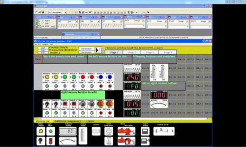
Good morning. My name is Mariusz Suder. I'd like to present the new process simulator PSPLC. PSPLC this universal process simulator can be used for building various technological models. PSPLC - is designed to work with PLCSIM v 5.x the part of Step7 and TIA Portal the Siemens™ PLC programming environment. There are plenty of typical devices and parts of industrial installations to choose which can be easily put or laid on the screen by simply selecting or dragging them. (...) PSPLC is the reliable process simulator. Useful for testing the PLC programs while they are executed or for learning programming the PLC controllers. Due to the intuitive user interface building models is quick and setting the devices easy. Colourful graphics, animations and high quality simultaneous sound. Language versions: English, Polski, Deutsch, Русский. Two units systems to choose: Metric and British Imperial. OS: Win XP, WIN 7 For further information please visit my internet site: http://www.sudermariusz.com.pl/psplc_the_plc_process_simulator.html http://www.sudermariusz.com.pl/plc_programming_examples.html Download PSPLC PSPLC can also be downloaded from: mrplc/download/siemens/demo
-
Version 1.1.0
179 downloads
PSPLC - the PLC process simulator, version 1.1, July 2017 Description: "PS PLC" - the PLC process simulator is designed to work with PLCSIM v 5.x the part of Step7 and TIA Portal the Siemens™ PLC programing environment. This universal process simulator is used for building various technological models. There are plenty of typical devices and parts of industrial installations to choose which can be easily put or laid on the screen by simply selecting or dragging them. (...) Language versions: English(full), Polski(pełna), Deutsch, Русский. There are also two units systems to choose: Metric and British Imperial. press.bmp -
View File psplc PSPLC - the PLC process simulator, version 1.1, July 2017 Description: "PS PLC" - the PLC process simulator is designed to work with PLCSIM v 5.x the part of Step7 and TIA Portal the Siemens™ PLC programing environment. This universal process simulator is used for building various technological models. There are plenty of typical devices and parts of industrial installations to choose which can be easily put or laid on the screen by simply selecting or dragging them. (...) Language versions: English(full), Polski(pełna), Deutsch, Русский. There are also two units systems to choose: Metric and British Imperial. press.bmp Submitter Mario980 Submitted 07/13/17 Category Demo Software