Search the Community
Showing results for tags 'address configuration'.
Found 53 results
-
Hi all, I am working on a safety PLC conversion project, for which I need to identify the input word address configured on a PSS AI IP card. The manual from the official website shows the address configuration via a DOS tool. I do have PSS SW PG WIN 4.9, but the project file has been created with PSS WinPro 2.3. Within this software there is only the option to configure how the input channel behaves, not which input word is used (see attached screen grab). Anyone with a distant memory if the addresses can be set with PSS WinPro?
-
Hi, About SmartSlice: „Smart Analog I/O performs data pre-processing to help you reduce PLC programming. Scaling and alarms, and even totalising or rate-of-change calculations are handled inside the unit.” How to get to this honey in case of GRT1-ECT bus coupler and NJ101 EtherCAT communication? What means “Configuration Tool” in W18E-EN-02 “GRT1-series EtherCAT Communication Unit Operation Manual”?
-
Hi everyone, I have a question for you all, Is possible to configure CJ2M-CPU11 with tags trough network configurator to connect Control Logix PLC using EthernetIP? I did a configuration with CJ2M-CPU31 and Control Logix PLC with no problem, but now I need to communicate CJ2M-CPU11 with Control Logix PLC using EthernetIP. Some of you did this configuration between this two PLC before? Regards!
-
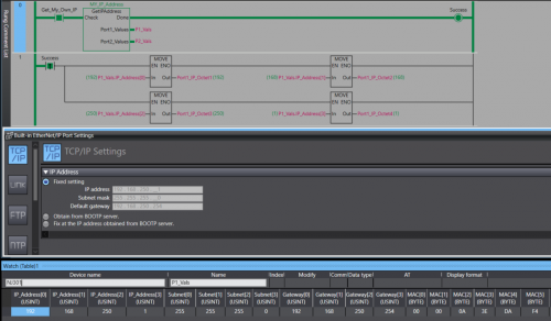
View File NJ/NX Get IP Address A Library containing a function Block that can be run on any Omron NJ or NX PLC. The Function Block will retrieve the host PLC's IP address, Subnet Mask, Gateway, and MAC Address. The Port Details are presented through 2 structures , 1 per-port. In the event the PLC only has one port the structure for Port 2 will be blank. Submitter photovoltaic Submitted 12/12/22 Category PLC Sample Code
-
Version 1.0.0
76 downloads
A Library containing a function Block that can be run on any Omron NJ or NX PLC. The Function Block will retrieve the host PLC's IP address, Subnet Mask, Gateway, and MAC Address. The Port Details are displayed through 2 structures , 1 per-port. In the event you only have 1 Ethernet port then the structure for the 2nd port will contain all 0s. Data Format: IP Address - USINT[4] Subnet - USINT[4] Gateway - USINT[4] MAC - BYTE[6] (hex value) Access the retrieved details by the typical parent-child tag structure. ex. Port_1_Detals.IP_Address[0] will get the first octet of Port 1's IP. Tested on: NX1P2, NX102, NX502, NX7, and NJ301 IMPORTANT: This Function Block should not be run immediately after startup. Allow the PLC a few seconds to establish a connection with the Ethernet network. -
I have several machines that use the RJ71EIP91 module. I have not had any issues until now. I do not have the original apa file. I upload the configuration and try to restore it from the configuration.apa file, it does not show everything that is connected to the card or programmed in the PLC. when I verify this it says that the configuration is a mismatch. I have several of these scattered throughout the factory and I don't have this problem anywhere else. Is there a solution to this problem?
-
Is there an efficient tool to manage and validate CX-Programmer addressing. Requirements: - Highlight Duplicate Address allocation - Compact/Defrag address range to avoid wasting memory space. Note: - Any FINS addressing will have to be reconfigured - This approach assumes symbol use rather than direct addressing in the logic.
-
It will de nice to have an option for getting a cross-reference report for the AT address used on programs , as is now its easy to make mistakes double setting the same AT address on a program , specially this days that supplies of NA screens are not always availiable and using memory address is necessary for NB screens and SCADA communication and is difficult to keep track of the used address on a program , some times in global or in internals, right now its easy to make a mistake and use the same address twice , and this wont be detected on the compiling
-
Hi All, I just start to setup a rotary servo (rotary transmission load type) and the designer pass me the spec of gear ratio 1:100. In my motion scaling page, I set Transmission I:O as 1:100 and then scaling unit is just position unit with 1:1. However, when i jog my rotary servo, it does not reflect the actual position in degree, so I went to read through the manual but still cant quite get how should i configure my scaling so that I can see that when the motor is rotating, i can see it rotate how many degrees? I try to set scaling 360 degree to 1.0 load rev, and the position feedback seems like much more finer....
-

Zebra Industrial Printer and Allen bradley L18ER printing via Ethernet IP
AniAutomationIndia posted a topic in Allen Bradley / Rockwell Automation
Mail me for Help if anyone is stuck during coding and settings. -
Is there a way to run a compact logix program, while ignoring the the I/O configuration? I used to do this with other PLC's to help develop the HMI screens while connected to development PLC that does not have the full complement of cards that the end user PLC will have. Just lets me test logic that supports the HMI while working at home. I used to do this on other PLC's with just a CPU on my desk. Possible?
-
Hi I'm trying to set up Modbus RTU communication between FX3U PLC and a weigh module. I would use the ADPRW command using 0X03 to read the 16 bit Holding Register but in the weigh module the Data Address/Holding Register of the value I want to get is 400047 - 400048. How to translate the value in 16 bit? Thanks, Fabio
-
Hi every one, One of my machine i have to fix , has simatic pc unit installed that causing too much trouble and client want to replace it with simple pc with additional profibus card installed in PCI slot, is there any way to configure image of simatic pc in new simple pc
-
Hi, I've got a very old version of Wonderware, version 9.5, which isn't going to be upgraded anytime soon. I would like to configure a button to perform 2 tasks under "Touch Pushbuttons", ideally "Action" and "Show Window". I am unable to enable both at the same time, so I've been trying to write a script that would perform both functions, but so far unsuccessfully. Is this something that can be done, or is there another way to get around this problem? I would like the button to toggle a bit and to open another window with more controls. thanks
-

1734 Vhsc24 very high speed counter module
Raghvendra posted a topic in Allen Bradley / Rockwell Automation
Hello, I want to compare pulsed coming from flow meter with a constant value. And make a bit to high level when my set pulses are equal to present value in counter. I am using 1734 Vhsc24 module for this. If any body have sample program kindly attach it. -
Connecting Generic I/O module to Micrologix 1100
Josemarian posted a topic in Allen Bradley / Rockwell Automation
Hello All, Am a bit new to practical PLC applications. I was trying to configure a Phoenix Contact I/O module (1452916) on a MicroLogix 1100 PLC but it kept faulting out with the fault light RED. It would say "Major Error Halt S:1/13". The error description says I/O mismatch. The error code is 187h (see attachment). The Phoenix module has a cable with 19 pin positions for the 8 input. I connected the pin 17 and 18 to 24 volts and 0 volts respectively. Then because I was using input 5 I connected the pink wire to PLC input (I/1) 24volts and the White/Yellow wire to the PLC common. On the I/O configuration on RSLogix 500, I used "Other" ( See attachment) but did not know the vendor details. Could anyone help me with the steps on how to communicate with the module? I have also attached the PLC program I was running. Thanks -
Hello, I have been so many days trying to comunicate the multiway software trought a serial usb converter with the SCU31 device, using a omron function block to read a holding register, but I can't achieved it. Now Im receiving some frames on multiway, but there is always some errors. I was wondering if somebody in here that have worked previously with modbus and omron can be able to help me in how to configure everything corectly to be able to read the value from multiway, on the plc, and where is this value saved. I'll upload some captures to show what I have done till now.
-
Communicating between plc's with different IP's
plcaholic posted a topic in Allen Bradley / Rockwell Automation
I am trying to get produced and consumed tags set up between 2 1756 racks with different ip's. The 1st rack has an ip address 172.28.6.3. The 2nd rack has an ip address of 10.81.105.8. Would this be as simple as adding an EN2T card to one of the racks and setting the ip of one onto the same network? Or is there a better way to do this? -
Hello , I dont have experience with Mitsubishi PLC. I want to do a modification on the ethernet configuration but i dont have the source code . According the information that i read we can use GX IEC developer or GX developer but my question are : Can i upload and download the program with GX developer? Even if was previous developed with GX IEC Developer i will not do any change on the code only on ethernet configurations , add a MC communication. I have another concern about the profibus module. For the profibus is necessary another program right ? But if i don't want do any modification on the profibus is dont need it, right? My experience on Siemens when is necessary do a modification on the hardware configuration. I should have all the hadware configuration " right" it means if i have profibus i should have the right GSD to allow do modification on the configuration . But on Mitsubish i can´t understand that well . Regards Roberto Fonte
-
Hi guys, I've just completed pre-commissioning on a Mitsubishi project which uses CCLink. My remit was to get the CCLink network up and running which I eventually did but not without issues. Basically, my problem was to do with the number of bits and registers consumed by a station. I read in a manual that each station consumes 32 bits and 4 registers for read and 32 bits and 4 registers for write. On my network I had 3 ST1H-BT modules occupying 2 stations each and 3 non Mitsubishi devices occupying 4 stations apiece. My RWr address starts at W300 and RWw at W500. Like I said everything matched up and I/O checks completed successfully. My question is, and I've trawled through the manuals looking for an answer, how is the number of points calculate? For example my non-Mitsubishi devices they occupy 4 stations, Expanded Cyclic Setting is Octuple and the number of points is 896. How is the 896 calculated? Thanks in advance
-
Hello PLC experts, I am master student currently writing thesis. For this, I have a initial task of making some changes to PLC program (Just started getting to know about PLCs- complete beginner). I have a BECKHOFF cx 9020 PLC connected to my notebook using ethernet. I am using TWINCAT 3.1 (VS) as IDE. Firstly, I cannot find my PLC IP address connected to my notebook . I added the route in the Twincat and it shows the PLC is connected. When, I am trying to run a program (activate boot project), I am unable to login to the PLC. It gives an error "login failed for application port 851". What I undertood from BECKHOFF scripts, there is something wrong with the ADS ams net ID which I am trying to figure it out. I appreciate all the help. Thank you.
-
Hi everyone My system consists of 2 main stations with 2 CPU Q06UDEH and connected together by QJ71GP21S-SX module but I don't know how to link the address between these 2 CPU together? so can anyone help me? Thanks so much
-
We have an iQ-r R08cpu that will not display some labels or addresses. The PLC and the machine it controls run as expected. However, when we read from the PLC, some of the labels and addresses are not shown. Although it runs as expected, we are hesitant to make any changes or write to the PLC. There is a screenshot attached. Any advice or solutions for this?
-
Hi folks, I'm trying to communicate with an old CompactLogix L35E via Ethernet. I have already establish communication via DF1 Serial port and was able to go online but I Do not know the IP address to communicate via Ethernet. Can someone please tell me how I could determine the IP Address or create a new one ? This Controller was remove from a working machine. Any help will be highly appreciated. Thanks, Anthony.
-
hallo all, I want to ask if I click "read PLC Data" the "points" will appear, I use the QY18A output module that uses 8 points but there is no choice, the smallest is only 16 points. so I can't put 148 in the "start XY" column ... will it affect the I / O address in the program?