

Paolo_911
MrPLC Member-
Content count
141 -
Joined
-
Last visited
Posts posted by Paolo_911
-
-
This controller also supports Modbus-RTU protocol with which I am unfamiliar, so this may be a better or easier option to communicate with?
-
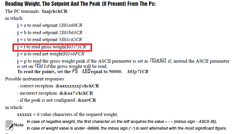
Hi guys, I'm trying to communicate with a scale controller (Rice Lake ACT20-AN) to read gross weight.
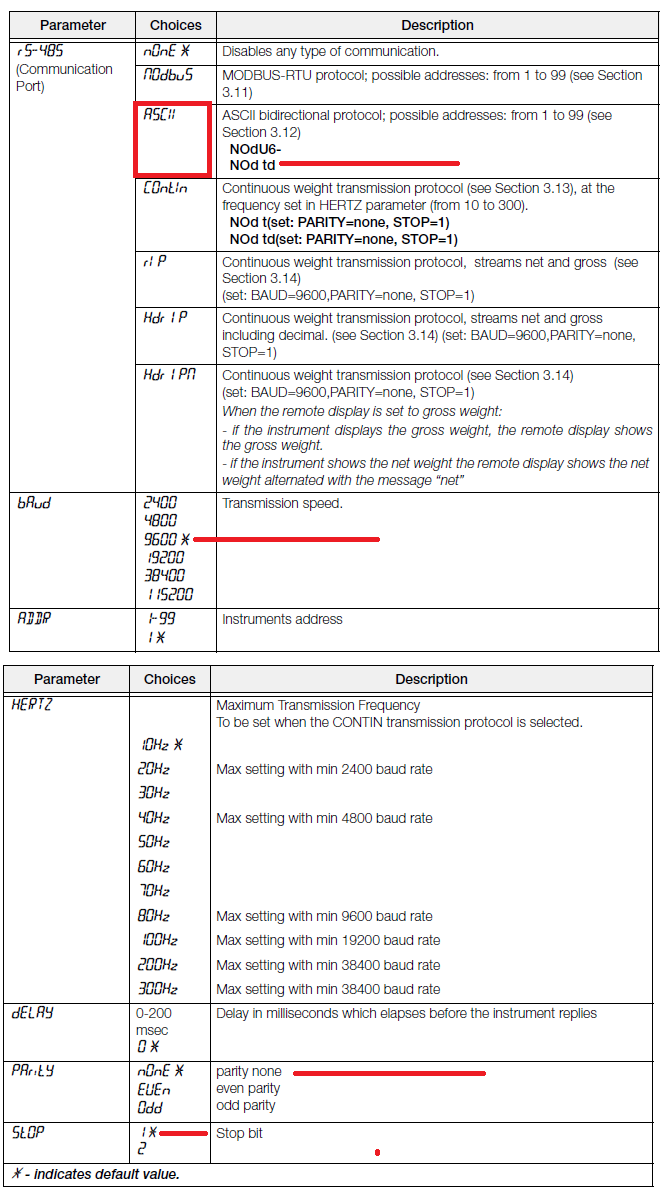
Scale controller: RS485, ASCII bidirectional protocol, Baud 9600, Address 1, Delay 0, Parity None, Stop 1
PLC: Channel 1, Data Bit 7 (unclear if it should be 7/8), Parity None, Stop 1, Sum check code Exist, 9600bps, Non procedural protocol (should this be bidirectional?), Station number 2 (should this be different than scale?)
I am using $Movp "$01t75CR" D6050, Movp K1 D6000, Movp K4 D6002, G.Output U8 D6000 D6050 M7000 which seems to work okay since M7001 does not turn on?
I do not get any data, however, when running Movp K1 D6100, Movp k7 D6102, G.Input U8 D6100 D6150 M7100 at the same time as the G.Output instruction.
I have attached the PLC program. Also, for wiring I wired the RS485+ to SDB and RDB, then RS485- to SDA and RDA as suggested by the scale controller manual. I then grounded the cable shielding along with SG and both FG connections.
Any help would be appreciated in figuring this out, thank you!

-
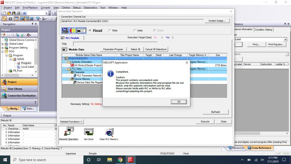
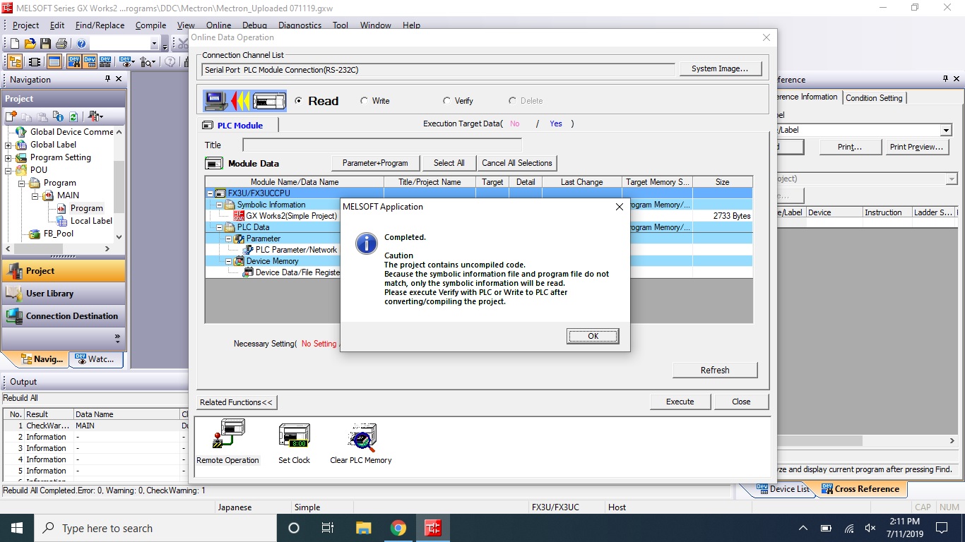
I am attempting to upload from a FX3U-32M to which I do not have a program for. Initially, I got an error message that the languages did not match, so I changed the program to Japanese. Then after uploading the program I received the attached error message (in the picture). I do not know what this means. When I open the program that I read, I can compile it, but with a lot of warnings, even a duplicate output. I'm concerned that I am missing something, and think the Local Labels might be an issue? I am only familiar with simple ladder projects, so maybe this was created using labels which I am not familiar with the process to upload that type of program.
-
The electrical department miraculously found a laptop still running Windows 95, I know right?! It is my lucky day. I also found a copy of the GOT program on a CD drive after digging around. I don't know how I'm getting so lucky! So I haven't tested the communication yet, nor do I really want to mess with it anymore, but I might if I'm bored. I will start on the upgrade process though now that I have the screens.
-
The port I'm connecting to says RS-232C beneath it, if that helps any. @Veganic Maybe it is just the fact that I'm not using Windows 95? I'm not sure how we are going to install Windows 95 to try that though haha! I may just be starting from scratch for an upgrade (YAY!)
-
@kaare_tI tried a RS-422 converter cable and still had no luck. I even tried all the different communication settings, but couldn't communicate. I'm not sure what I'm doing wrong.
-
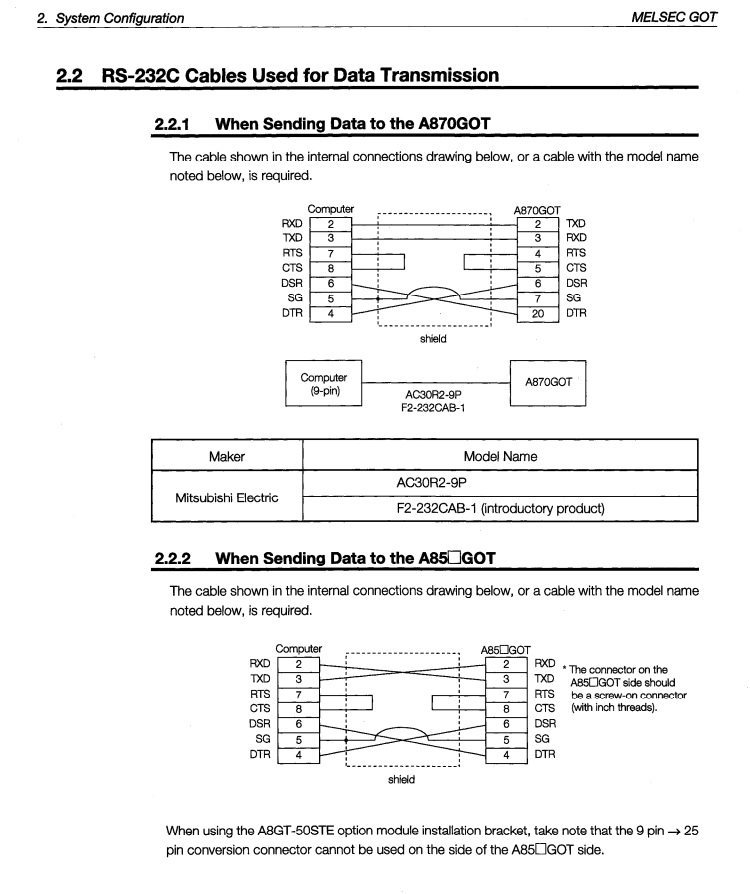
Sorry for the delayed reply. I finally came around back to this issue. Below you will see the recommended cable AC30R2-9P found inside the SW3NIW-A8GOTP Operating Manual in the section describing how to connect to the GOT. I noticed that this is to send data to the GOT, but would it be the same to upload data from the GOT? I haven't done anything yet to figure out how to convert to RS422 though to see if that is my issue.

-
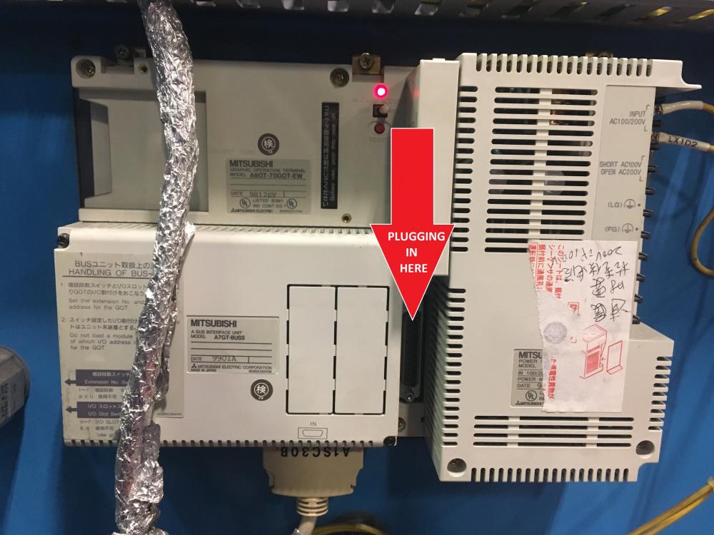
I'll check the cable again or see if we have another one kicking around. I only mentioned that I was using the RS232 port off the laptop. I am plugged into the RS-422 port (I'm guessing) on the GOT. See the attached picture for where I am connecting to the GOT to ensure I am attempting to connect in the right spot.
-
GOT: A8GT-70GOT-EW
Software: SW3NIW-A8GOTP Version 20N (downloaded free off Mitsubishi website)
Communication cable: AC30R2-9P (rung out pins to test and was recommended in GOT manual)
I am trying to upload the GOT program using an old laptop with RS-232 port and have tried all baud rates on COM1 in the software. No other COM ports show any connection on the laptop, which is expected. I have even tried changing the GOT-type (although I figured it would be A870GOT-EL). The other options for GOT are A870GOT-TFT, STN/A810GOT or A85*GOT-STN,L. I have also tried to upload from memory and memory card, which are options, with no luck.
I keep getting a connection failed message every time I try to upload. Any help will be appreciated. Thanks guys!
-
Nevermind, just found out that a Q is unable to communicate with the FX3U-ENET-ADP, but apparently it can communicate with the FX3U-ENET. I was given some code by Mitsubishi tech support to communicate via MC Protocol and will give that a try.
-
@Gambit We are also trying to communicate between a Q series PLC and an FX using MC Protocol. My question is, are we able to use the last function block you listed (...EthernetFX3QMC...) inside the Q series PLC program? We are hoping to capture (pull) data from multiple FX series PLCs using the Q as the master who reads the data. So is it possible to use that FB in the Q program to read data from the FX using MC Protocol?
On 12/14/2016 at 3:57 AM, Gambit said:There are some FB which simulate the MC protocol which you can download from the European Mitsubishi site.
Then you only have to create a port on on PLC. And use the FB in the other project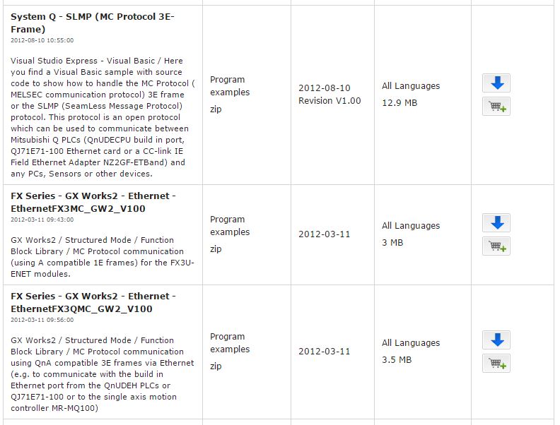
-
On 4/14/2017 at 7:09 AM, kaare_t said:Yes it does.
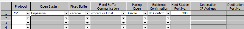
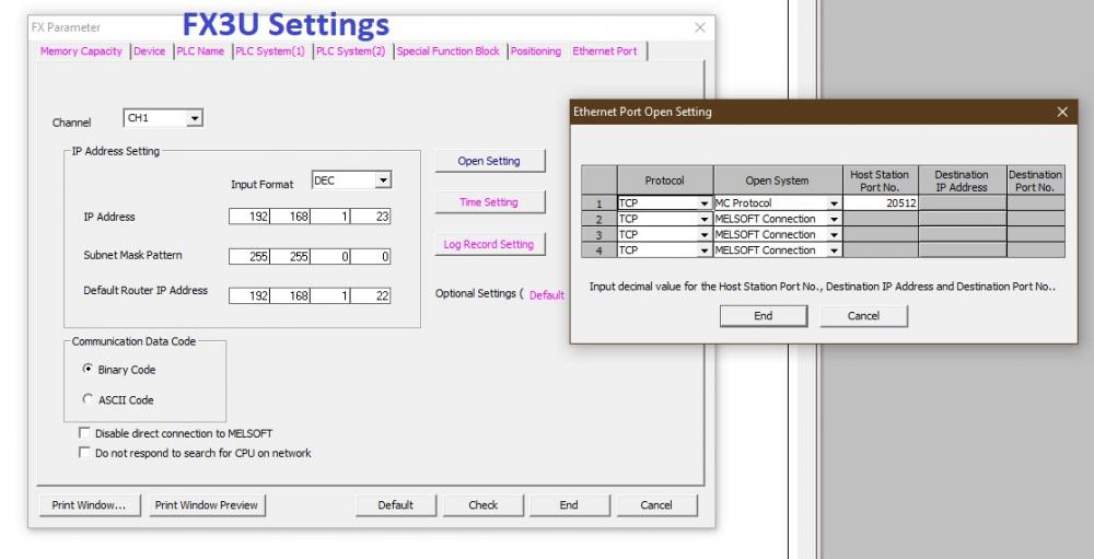
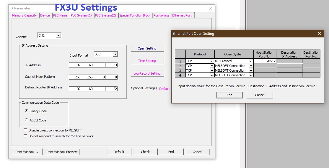
I am trying to communicate via MC Protocol from a Q03UDECPU with QJ71E71-100 module - through ENET switch - to an FX3U-ENET-ADP attached to a FX3U PLC. The FX3U-ENET-ADP only allows TCP > MC Protocol communication as seen in my attached picture. This is the only reason I'm now trying to communicate via MC Protocol, whereas before I was able to communicate through fixed buffer from Q to Q PLC (using a S.JREAD instruction). How do I pull data to the Q from the FX3U ? Do I need a Mitsubishi MC Protocol Function Block to do this or can I still use Simple project > ladder logic instructions in GXWorks2? Using the settings you posted - Unpassive - how does the PLC know which destination IP address or port to go and receive the data from (the FX3U at 192.168.1.23 port 20512 in my case) ?
Below are the FX3U settings I have set up to communicate through the FX3U-ENET-ADP:
 1 person likes this
 -
YAY! I got it to work with the QJ71E71-100 Ethernet card too now. Thanks Daniel for all your effort to help!
-
Thanks Daniel,
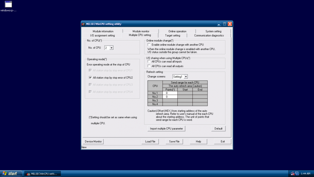
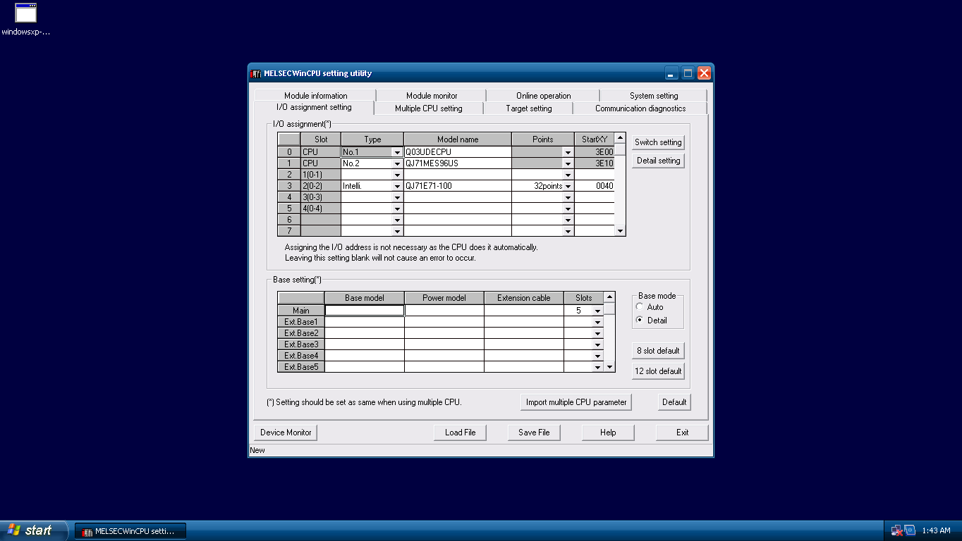
I got it to work finally! The only thing I changed inside the MES CPU configurator settings was the Base Mode. I changed it from Auto to Detail, which I have no idea what that does.

-
I'll need to check on the link parameter error, but I doubt I still have that since I don't have the Ethernet card in the rack anymore. That would be great to have a multi-cpu configuration, but what do you mean change the 2nd CPU type? How do you specify the type of CPU?
I'm thinking it all has to do with setting up the MES module settings to match the CPU parameters, but I could be wrong.
-
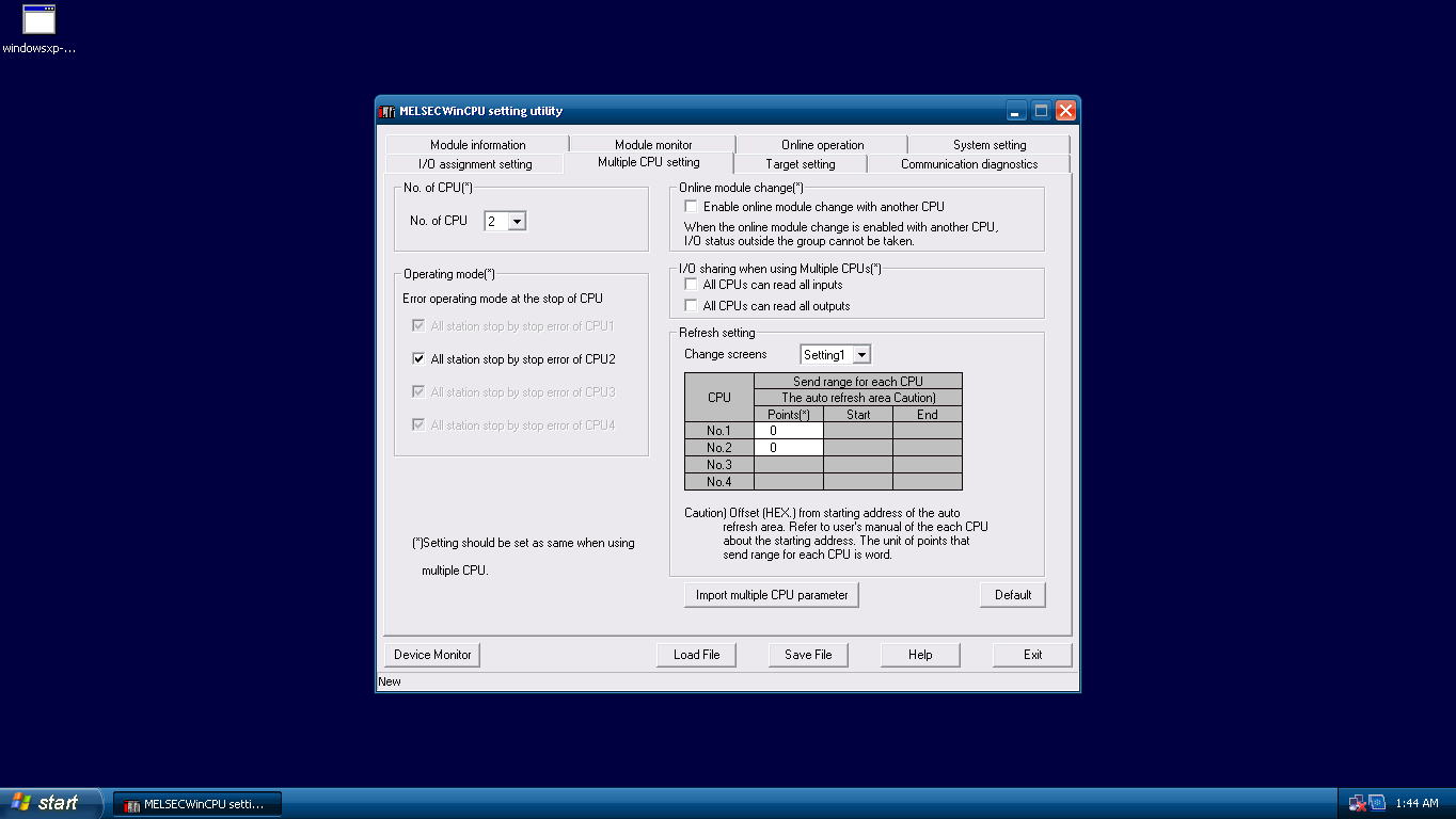
@collinsd70 - The above failed. I was successful in creating a program with just the PLC in the rack, but once I tried to add the MES module as a 2nd PLC, both the CPU and MES module faulted. I think I matched the parameters/settings, but it still won't work. The MES module takes up 2 slots in the rack, but I'm not sure how to specify that in the multiple CPU settings.
-
Thanks @collinsd70. I will try to run the rack with the bar essentials and gradually add modules like you said. That is great advice, thank you! When I get a chance I will upload the manual if I don't have much success in setting it all up. Thanks again. I will update later with my progress.
-
Still no luck. Please Help!
-
I just noticed that I left a spare in Slot 1, assuming I needed to with the MES module taking up 2 slots physically. I will try moving the QJ71E71-100 module to Slot 1 in the PLC parameters and MES module settings to see what happens. I'll respond back if it is successful.
-
The PLC and MES are faulted when trying to set it up. Any help would be appreciated.
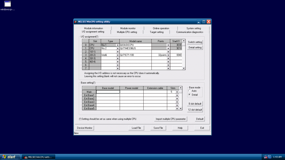
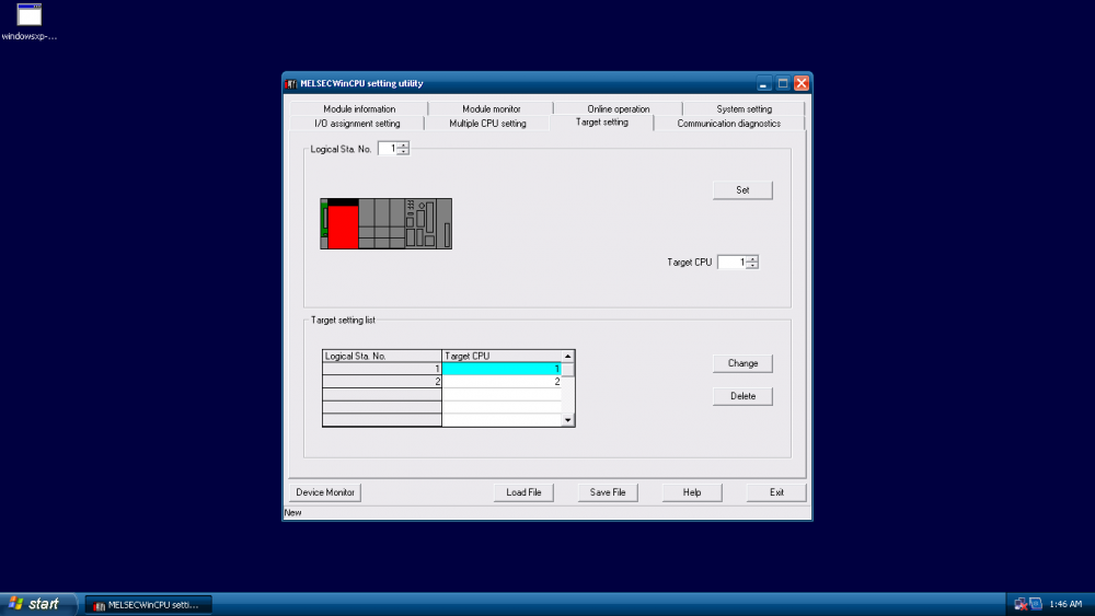
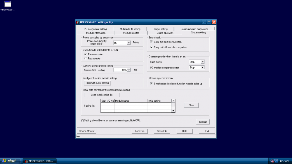
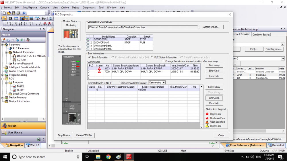
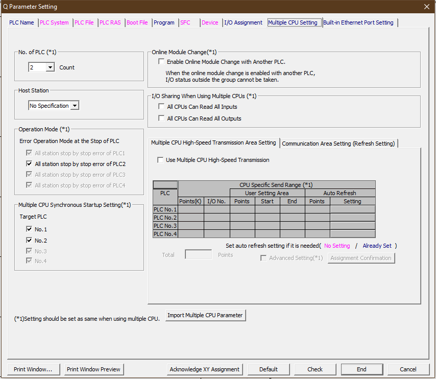
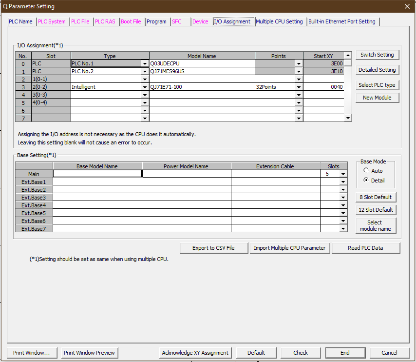
PLC Rack is as follows: Q03UDECPU (Slot 0), QJ71MES96US (Slot 1 & 2) and then QJ71E71-100 (Slot 3). Attached are photos of parameters, MES setup, and Error Message. I am not sure what I am doing wrong in setting up the MES module to match the PLC parameters. I imagine this is what is causing the error. Both the CPU and MES module are faulted with red blinking lights. I also was unable to change the Target CPU in the MES setting utility, even though I'm not sure I'm supposed to. I tried changing it to 2 (since the MES unit is the 2nd CPU) and when I change tabs, and go back, it is reverted back to 1, although still not sure this is the issue. I did "Write" the setting in the 'Online operation' tab, received a message saying the setting change was successful and then reset both the PLC and MES.
-
Okay thanks. I wasn't sure about this, and wanted to confirm that I could try to step through or use a timer to talk to different stations through one channel. I didn't want to bog down one channel, but I know you're right that it is quite fast. Thank you for the response.
-
I'm using a JP.Read Instruction and from my basic understanding I believe it communicates through a single channel. In the control data I need to specify word address of which channel to use. My question is, if I am trying to communicate with several Q03UDECPU PLCs (say 16 stations using the maximum 16 sockets of the QJ71E71-100 module) is it only possible to communicate simultaneously to 8 stations since it only has 8 channels? I'm trying to continuously read the data of 16 stations as fast as effectively possible, but not sure how to do that with only 8 channels to work with (I think the max channels is 8).
-
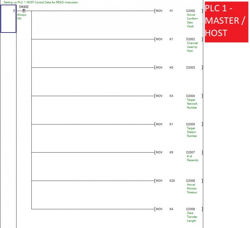
I believe I am using a crossover cable between the two QJ71E71-100 Ethernet modules, but maybe I need a switch in between (?) . My laptop PC is connected via USB to PLC1. I did discover my first mistake, as I had the network number wrong in my control data D2004. Now I don't get an instruction error, but now a Comm error which I need to look into. In a loopback test it appears that PLC1 is not able to communicate with PLC2.
-
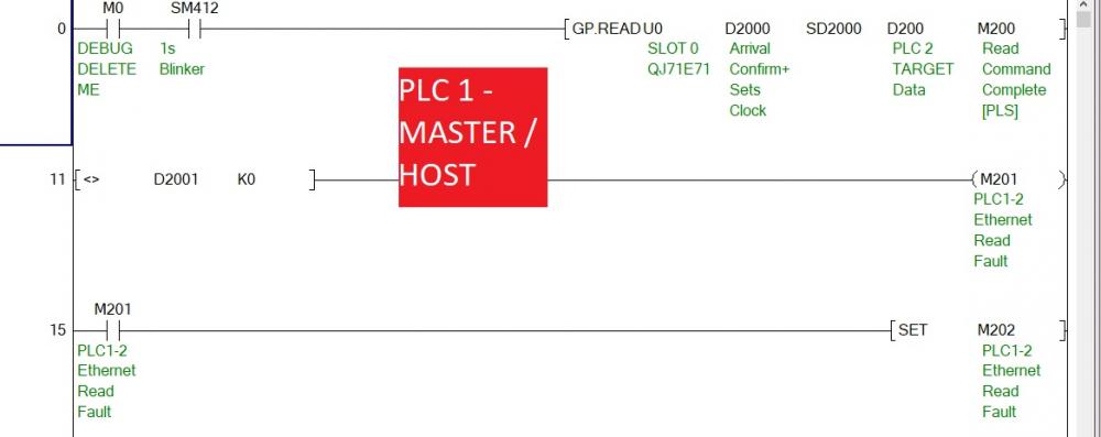
In a simple bench test, I am trying to communicate between two Q03UDECPU PLCs through a QJ71E71-100 module (both in Slot 0 on the racks) through a 3 foot Ethernet cable. I get an instruction error when I try to execute the GP.Read instruction. It doesn't give any indication why it fails, but the CPU faults out trying to execute this instruction. Any help would be appreciated.


If you want, I can attach both PLC programs.


RS485 to Scale
in Mitsubishi
Posted
I figured as much. I started to look into that yesterday and will work more on that today. Do you happen to know which are the dedicated instructions or function blocks? I started looking into the function blocks, but have zero experience with them. The ones I downloaded (recommended from this forum), I couldn't even drag into GxWorks2 so had no luck there.