Search the Community
Showing results for tags 'ascii to real number'.
Found 84 results
-
We recently obtained a new Vendor ID (VID) Number from ODVA, 1477 for the purposes of developing an EtherNet/IP scanner device. When we try to use that number with the Allen-Bradley PLC & Studio 5000 Logix Designer, our data type REAL's are showing up in Studio 5000 as SINT's. We have seen this mangling of data types before when using the Omron VID, 47 with the same Allen-Bradley PLC/EIP Scanner. The data types are being misinterpreted, or mangled from REAL to SINT, e.g. the *.eds file defines 32 REALs for Input and 32 REALs for Output, but within Studio 5000 we see 128 SINTs each for Input and Output. It is as though the Allen-Bradley/Studio 5000 database does not have our Vendor ID. When I change the *.eds file, Vendor ID Number from #1477 to #1 then we see the *.eds file being properly read and interpreted, e.g. 32 REALs for Input and Output show up as 32 REALs each. Does anyone know what file we need to modify in Studio 5000 ??? We want to add our Vendor ID #1477 to that file. Hardware: EIP Scanner: Allen-Bradley Compact Logix L18ERM EIP Adapter: Delta Tau Power PMAC Motion Controller (EIP OpeNer Stack) Thanks in advance! See screenshots below. within Studio 5000, see screenshots
-
Hello all i'm looking for some software to record a 100 plus channels maybe with an ascii string from a PLC? i want to be able to assign each channel with a unit and a range, flagging feature would be nice. - selecting the channels i want to view - auto start recording - save file and start new automatically -view and create reports preferably no additional hardware because of the amount of channels. this is to record an operators every move so in events of damage or plant failure we can quickly identify the problem (point the finger) many thanks dan
-
fx 3g modbus.gxw
-
I want to do a calculation in the FX3u-48MT ESS and combine it with the input from HMI GOT1020. By the time i put input in the HMI with real number, and i calculate that with some equation just like in the manual as seen in the picture. I was confused when the result in the DINT is too many and in the pulse, it got minus, when it should be plus. Is there any way to fix this ? and how to round up the result correctly ? I really appreciate your help. Thanks in advance.
-
I current have 2 variable: Displacement vs Pressure. I need to draw a real time graph on Comfort Panel. The problem with using just f(x) trend is that the minimum time between updating a point is 0.5 sec and that is for ever in my application as the whole cycle last only 5 sec and I have to plot 500 points in that time. Is there a way to do real time graph using Historical data without any time delay. If anybody can guide me through any sample program or material would e helpful. Thanks
-
Hello. This is my first post and I hope someone has a solution. I have a program calculating Gal/sec adding to a running total and have up to the end. Using REAL I can accumulate up to 16,777,216 (2^24) and using DINT up to 2,147,483,648 (2^31), but I need to have my registers continue past these limits. I've read through many topics here and have tried the Rockwell Knowledge Base but can't seem to find a solution that truly works. I have gone so far as to transfer the DINT to a string, cut the string into pieces and reassemble them in an Odometer type concatenation. If anyone has a suggestion, I would appreciate it. I know I'm not the only one with this problem. PS & BTW - I'm using Studio 5000 v24 with a 1769 L33ER
-
Hi, New to the site, seeking help with an Inkjet Coder that the company I work for recently purchased. A customer is wanting us to have the printer message selection automated, because parts got out with the wrong print on them. We purchased a Linx 5900 and want to use the serial port on a slc 5/03 to send a command to select the message based on a selector switch's position. I've been pretty desperate trying to find help with this issue, because this is my first time messing with a printer. I've got the AWA instruction set up and it will send a string, but I'm not sure what to have in the string or if I have everything configured right. I've attached the program for you guys to look through, the AWA instructions are at the end of LAD 13. I'm using the serial port to make changes to the program then hooking it into the printer to try the changes out so its a bit frustrating, but I don't have a pc with windows xp sp2 so using the DH485 port is not an option. Any help will be greatly appreciated. CNTRPUSH_4_2017.RSS
-
I would like to send a character on a Micro830 using ASCII. I wish to send the character to a pc by using Real term or terra term on PC. Can somebody please let me know how can I configure the ladder diagram, I tried various commands including THE AWA, AWT and also the MSG_modbus however I can initiate the communication. I think that I am missing something cause I don't have a reference ladder diagram. Thanks
-
I'm using a 1769-ASCII and need help with one part of it. I have no issues with sending data. The manufacturer shows the following as the process... My question is: how do I evaluate the XON\XOFF? The machine states "This communication protocol tells the status if it can receive any data or not to the host by sending "XON" (HEX 11H) or "XOFF" (HEX 13H) to the signal line." I never receive any data so I'm not sure what's wrong or if what I'm doing is correct. The attached file is same code downloaded from AB's website which is what I based my code off of. http://search.rockwellautomation.com/search?client=samplecode&oe=UTF-8&ie=UTF-8&output=xml_no_dtd&proxystylesheet=samplecode&site=sample_code&getfields=*&lang=en&hl=en&sort=date:D:L:d1&wc=200&wc_mc=1&ud=1&filter=0&q=ASCII 62119.exe
-

FactoryTalk View DINT to ASCII conversion
DennisP posted a topic in Allen Bradley / Rockwell Automation
Would someone please help me how to convert an integer to ascii? For example if the output tag is an ascii string, of 3 characters and my numeric input is integer. When user input a value of 5, I would like the input value to be convert and assign to output ascii string tag of "005". How do I set the conversion format in either tag assignment or tag expression? -
ok i have a rotary encoder to a HSC on my tm221, im converting that to ascii and outputting the value to a lascar HMI over rs232. example of value sent: 1234 value received: 2143 there don't seem to be any options to set the LSB or MSB , any ideas?? Dan
-
Hey Guys!!!! I'm trying to use ASCII 8 bites in TWIDO PLC and on MOD BUS TCPIP it connected to WinCC , where I'm trying to read the ASCII in as a STRING char that to in 8bits. The problem I'm facing is that it is getting swapped like if I'm writing VA in PLC then on SCADA it is showing AV. In WinCC there is no setting for word swapping. Therefore Kindly help me for this in plc end
-
ASCII Code 8 Byte In Twido
varun_pandey posted a topic in Modicon / Telemecanique / Schneider Electric
Hey Guys!!!! I'm trying to use ASCII 8 bites in TWIDO PLC and on MOD BUS TCPIP it connected to WinCC , where I'm trying to read the ASCII in as a STRING char that to in 8bits. The problem I'm facing is that it is getting swapped like if I'm writing VA in PLC then on SCADA it is showing AV. In WinCC there is no setting for word swapping. Therefore Kindly help me for this in plc end -
Converting 16bit Word (INT) into REAL Decimal Number (Via SINT[2])
jake4eng posted a topic in Allen Bradley / Rockwell Automation
I am having problems expressing an ANALOG OUTPUT 16bit INT word (0-10V Proportional Valve Voltage) as a REAL decimal number. From my understanding the word is divided into 2 (8bit) bytes...one representing the whole number value and the second the decimal value. We're using BL20 I/O Module (german therefore LSB first I believe). I need to MOV/COP (read) the value, CONVERT it into a REAL number, Manipulate the REAL VALUE, then CONVERT the MANIPULATED REAL Value back into a 16bit INTEGER & WRITE the NEW Integer Value into Proportional Valve Voltage Location. I also have a similar situation regarding our Incremental Encoder. In this scenario the pulse count is obviously a whole number (no decimals) where 4 (16bit) bytes represent the REAL Count Value.. I have read other posts on similar conversion topics and understand the general premise, but I'm having problems specifying write parameters.. - i.e. writing bits 0-7 from an INT into SINT[0] (HIGH BYTE representing the whole # value? ) and writing bits 8-15 into SINT[1] (LOW BYTE representing the decimal value) THEN CONVERTING into REAL # (Voltage fed to Proportional Valve) ...manual section... page 282&283 http://pdb2.turck.de/repo/media/_us/Anlagen/d300717.pdf - i.e. writing bits 0-15 from INT[0] , INT[1] , INT[2] and INT[3] into a LINT (not sure if correct) THEN CONVERTING into REAL # (Encoder Count) ...manual section... page 17 (current count value) http://pdb2.turck.de/repo/media/_en/Anlagen/D301224.pdf ANY SUGGESTIONS WOULD BE GREATLY APPRECIATED... project file if interested.. https://sites.google.com/site/lyncedrgb/eva/untitledpost-2/StellaPLC.ACD -
I have been using Mitsubishi PLCs for the last 17 years and to be honest whenever I need to shift data I generally use an Arduino. But I have existing PLCs that each need to be connected to a PLC running Biometric Readers. The handshake between the PC in a box (running the biometric readers) and the PLC (running an access control turnstile) will be 8 bit ASCII code via RS232 connection. I am struggling to find any working examples of code to run an RS232 BD card on an FX3G PLC, I have set up an FTDI RS232 UART and I can see data coming in from an Arduino but I can't get the FX3g to send any data via RS232. I can't even get the PLC to communicate. Unfortunately the tech support offered here in the UK is awful. Any help would be appreciated. Regards Julian
-
Hello, I am using an NJ301 PLC with an NA series HMI. I am communicating to the PLC via FINS protocol using the DotNet FINS UDP application by Jay Anthony found under the downloads section. I am finding that when I write a string to an address, the bytes order are reversed. For example, I am writing the string 'Test' to variable 'FINS_String', which is a String data type at memory address D20. My FINS command is the following: 010282001400000254657374 0102: Write 82: Data Memory 001400: Address 20 0002: Write 2 words 54: T 65: e 73: s 74: t The value that appears on the HMI and in the watch window is 'eTts'. If I write 65547473 (eTts) as my command, it appears correctly as 'Test' on my HMI. I debugged the application and I see that the byte array is being sent in the correct order, so I'm not sure what the matter is. I can't imagine that to pass a string through FINS protocol the hex values need to be switched every time. Any help would be appreciated. Thank you for your time.
-
Siemens S7-300........I can convert from INT to DI.....and from DI to REAL. I don't see any standard method of going backwards from REAL to DI and from DI to INT My actual application needs to go from REAL to INT (DI to INT is kinda dumb) Thanks, Bob
-
All, I have a 1769-L24ER-QBFC1B processor with a 1769-ASCII card that I am trying to get working on the bench. I have a standard serial cable hooked up from Channel 0 of the ASCII card to the COM1 port of my computer. All I'm trying to do at this point is a simple bare-bones hello world program with a terminal (termite or putty) so that I can verify my setup and understand how it works before I try to implement it on the plant floor. I have the card set up in alternating mode and am using the pre-canned program found starting on page 35 of the user manual(1769-um012) .This is my first time using the ASCII card I am familiar with the CompactLogix processors and the RSLogix Suite. Any insight you can give would be greatly appreciated. Thanks, Lucas
-
Hi! I just started with PLC programming. I am trying to get the time between a output signal and a input signal. The problem is that the time is ~200 ms but when i measure it with this code: TONR(Timer1); IF PosFeedback <= PosFeedback_Min & not Timer1.Reset THEN Timer1.TimerEnable := 0; FullCloseDeltaTime[1] := Timer1.ACC; Timer1.Reset := 1; END_IF; IF (move & not Move_LastScan) THEN //Start timer Timer1.TimerEnable := 1; Timer1.Reset := 0; END_IF; Move_LastScan := move; i only get even values in intervalls of 50 ms like 150, 200 and 250 ms. I have changed the real time sample rate to 11 ms so i don't understand why i don't get a more exact result. And i can see in my trend that the time isn't exactly 150, 200 or 250 each time. I i tried and time my own click on a button and i see the problem is the timer, i only get values in an interval of 50 ms. Is there a way to make the timer more exact?
-
Micrologix 1400 - Read more than 82 ASCII characteres
GATI_1976 posted a topic in Allen Bradley / Rockwell Automation
I have a Micrologix 1400 and one PC which sends 102 Characters in RS-232. I need to read all characters with Micrologix 1400, Is there any way to read all characters? I know the limit of ARL and ARD instruction is 82 characters. I do not know if two ARD instructions could read all characters. Do you have any experienced like that? Could you help me? Thank you in advance -
I need to know if there is an easy way to convert a hex value to ascii without going through all of the math. In the ContolLogix 5000 software, I can find how to do a string to decimal (STOD), but the problem is the initial value. For example, the hex value for ASCII 3 is 31, ASCII 4 is hex 32, etc... If I do a STOD to create a string from the value of hex 31, I get a string of: '31'. I need to send this value out to hyperterminal and read a 3, not 31. If it was only reading one source and did a simple subtract and mov commands for the values of 0 through 9, that would not be a problem. However, my problem is that I am continuously reading multiple valuses from several sources and I don't want to have to write the code for each character from each source. I could do and AOI or UDT, but isn't there a simple instruction in the logic?
-
Version 3.11.2.0
422 downloads
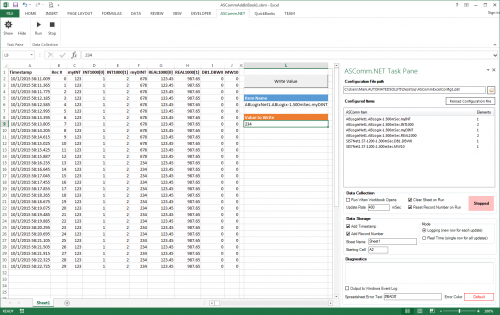
ASComm Excel Add-in is a simple to use, non-programmatic way to populate Excel 2007 - 2021 (version 16) spreadsheets with data from PLCs, instrumentation, and other process hardware. ASComm Excel Add-in uses built-in drivers for Modbus/TCP and Modbus RTU/ASCII communications. No OPC, DDE, external drivers, or programming required -

[Demo Software] - Excel Add-in for Modbus/TCP Data Logging
Automated Solutions posted a topic in Download Comments
View File Excel Add-in for Modbus/TCP Data Logging 3.6.8 ASComm Excel Add-in is a simple to use, non-programmatic way to populate Excel 2007 - 2016 spreadsheets with data from PLCs, instrumentation, and other process hardware. ASComm Excel Add-in uses built-in drivers for Modbus/TCP and Modbus RTU/ASCII communications. No OPC, DDE, external drivers, or programming required Submitter Automated Solutions Submitted 03/01/16 Category Demo Software -
Hello all, I was asked to check if there is a PID real - time software which automatically calculates PID loops parameters and update the PLC registers or HMI ( by OPC server etc.) when the process is working and "breathing". REAL-TIME. Not PID simulator or PID tuner based on measured data, but a software that will calculate and update the PID parameters in real time while maintaning several PID loops simultaneously. Are there any suggestions? Thank you, Olesia
-
Dear, I need some help with an application in ml1500 with the RTC . I need an exit is enabled by days of the week . I´m programming in Rslogix500. Program follows the image. If possible help me. Thanks Daniel.