Search the Community
Showing results for tags 'Fatek timer counter second'.
Found 95 results
-
hi: in Omron that is a command to count how many bit that are in ON state, any similar instruction in GX Work 2? Thanks
-
Version 1.0.0
208 downloads
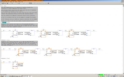
This logic demonstrates the construction and cascading of counters that count from 0 to 9. This logic also illustrates the construction of counters that count from 1 to 10 (not useful for cascading). The difference is mainly in the comparators used to reset the counters. There is one small additional detail. Can you find it? -
View File FC3 Counter Demo This logic demonstrates the construction and cascading of counters that count from 0 to 9. This logic also illustrates the construction of counters that count from 1 to 10 (not useful for cascading). The difference is mainly in the comparators used to reset the counters. There is one small additional detail. Can you find it? Submitter pop29684 Submitted 03/24/16 Category PLC Sample Code
-

STEP7 Professional V13; FB Declaration Static: Data type TON is not allowed here
Traloch posted a topic in Siemens
Product: STEP7 Professional V13 Reference: FB Declaration Static: Data type TON is not allowed here Description: ++++++++++++++++++++++++++++++++++++++++++++++++++++++++++++++++++++++ Hi, I'm using Step7 Prof V13 SP1 upd7 & WinCC Adv V13 SP1 upd7. In my project I'm using a 312CPU, Article No.: 6ES7 312-1AE14-0AB0, Version: V3.3 & TP1500 Comfort, Article No.:6AV2 124-0QC02-0AX0, Version:13.0.1.0 My Issue: I've taken previously used FB from my Global library and inserted it into my new Project. In this FB I've declared an IEC Timer (TON) in the static section of the FB. When I go to upload to the PLC after TIA carries out the compilation I get error message 'Data type TON is not allowed here'. I've tried creating a new FB to test and had same issue for CTU,CTD,TOF. See attached pics This is really strange as it has always functioned before! Has anyone seen or heard of this issue before? I'd appreciate any help, Cheers. -
Hello, I hope you are all having a great Wednesday. So I was wondering if this is possible, and if so, how to do it. What I'm trying to do is get a real time speed of my hydraulic cylinder using a transducer, a 1769-HSC high speed counter module, and a 1769-L36ERM processor. Kind of like a speedometer in my car. I would like the number in inches/ second. We use a hydraulic proportional valve to control a cylinder that we use to pump molten lead into our die cast machines. Back in the day they used to use limit switched that rest on a tail rod attached to the cylinder shaft to get an approximate stroke length. It was very crude, but it worked for what it was. I'll explain a little more, in case I'm not explaining it very clearly. So on most of our machines the maximum stroke length of a normal shot is about 11". We have different "stages" to the shot. Stage one is typically from 0" (when the shot is all the way returned) until about 1.5", at 1.5" the valve stops and there is a shot delay for 1 second (vacuum draws some lead into the goose neck and into the beginning of the mold), after the delay second stage starts, second stage is from 1.5" to 4", third stage is from 4" to 8" and fourth stage is from 8" to 11.5" or until the shot timer finishes timing, and then another valve switches, and the shot starts it's return. We have the different stages because we typically shoot the cylinder slower at first, and then delay and then almost maximum velocity. We control the velocity with an analog output to a solenoid on a hydraulic valve. For example, for the first stage we may open it up 20%, then 0% during the delay and then 85% during second, third and fourth. Sometimes we play around with different shot delay times, different shot velocities, sometimes 3rd may be faster than 4th, ect, to get the best die casted parts. Anyways, so in the past they would use limit switches. One was a button head style that when the shot cylinder shaft was all the way returned, it made the switch, and we knew the shot was fully returned. One was set at 1.5", 4", 8" etc. They all, except for the shot return switch, were roller style limit switches. They were all made, and once the shot reached that stroke length, they would come off the rod and we would know we were in that next stage. So it was very crude. If you wanted to adjust the stages you would have to climb up on top of the very hot molten lead pot, mark where the limit switch currently was (in case you needed to put it back) loosen the bracket, try to make a measurement and guess how far you moved it. It was crude to say the least. Some of our older style machines that don't need much tweaking still use the limit switch style positioning system. Most of our new machines all use a VisiTrak transducer. The shot cylinder rod that is attached to the cylinder shaft is actually threaded and then has a very thing layer of chrome plating. The transducer sits against the shaft and counts the threads. It transfers those counts to a Very High Speed Counter module in our PLC I/O rack. We have a CompactLogix L36ERM processor and we use a 1769-HSC as the VHS Counter. Then we just do some math in the PLC program and we are able to get shot stroke in inches. We set different compare instructions, for example when: Shot_Stroke is greater than or equal to 0 AND Shot_Stroke is less than or equal to 1.5 then 1st_Stage_Bit is active. We set up different numbers for all the different stages and still use the button head limit switch as a second method to confirm that the stroke is fully returned. The counter is very fast. We are able to know what the shaft stroke is at any given point. We currently do some math using the distance of each stage and using timers to calculate inches per second of each stage. That way we can have a nice Speed number in inches/second that we can use to make different adjustments to the shot. Typically the first stage is about 7"/second second is: 24"/second third is: 42"/second and fourth is 2"/second. But I want a real-time, current speed, not just the speed that it traveled through each of the stages. Ok, after all of that explaining, I'm finally getting to my question. How would I logically write a set of instructions that could give me current speed in inches per second. Like i said, I am able to calculate the speed of each stage, after the shot has completed the stage, I just divide the distance of the stage (in inches) by the time it took to travel through that stage (in seconds). But I would like to have a real time speed, kind of like a speedometer on a car. Is this possible? I know that the scan time on this processor is very fast and the high speed counter module counts very fast as well. How do I do the math to get a real time speed in inches/ second? Sorry for the very long post. I just thought i would give you a background on what we are doing/ would like to do. Thank you very much.
-
GX Works2 Timer Example View File OUT_T on of delay timers in GX Works2 Submitter HwT Submitted 12/12/15 Category PLC Sample Code
-
-
Hi, I am new to the forum and relatively new to PLC's and I am working on a project that controls several pumps and I would like to install a off delay timer that can be adjusted on the HMI for individual pumps, is this possible ? I am using Siemens TIA Portal V13 and I have a KP1200 comfort panel along with a S7-1500 PLC Any help would be greatly appreciated
-
Could anyone tell me that how can we use/recall Q bit of timer in FP0R. As we can use DN/TT in Allen Bradley
-
FB_TIMER_ON_OFF The FB is a part of RTC library and implements a timer, based on RTC, for ON and OFF a control bit, e.g. to turn ON/OFF a load in the time interval, and can be easily added into your program in desired quantity. The FB is supplied with E (Enable) input, EO (Output to Control Bit), and can operate in one of two modes: HMS = Hours + Minutes + Seconds (daily timer) MDH = Month + Date + Hours (yearly timer) Each setpoint of ON and OFF time settings should be represented as Array of INT [0...2] type and contain a time data according to the chosen mode. Thus, for example: - in HMS mode: a control bit can be turned on at 02:03:14 am and then turned off at 06:04:17 pm, or turned on at 05:12:27 pm and turned off at 07:06:22 am; - in MDH mode: a control bit can be turned on 3th February at 02:00 pm and then turned off 4th June at 05:00 pm, or turned on 12th November at 03:00 pm and turned off 6th March at 10:00 pm. If the values of both time settings are the same, the FB output will not be activated. Supporting PLC CPUs: All FX Program memory: - 34 steps per each FB instance - 4 steps for entire project (reading from RTC) System variables: M - 3 bits (for entire project) The library is compatible with GX IEC Developer and GX Works2 software . https://plus.google.com/105445006108716761629/posts/Z4v4F11s4Bz
-
Turning inches traveled per pulse (a real number) to inches per minute
487mcgill posted a topic in Allen Bradley / Rockwell Automation
I am currently trying to get my program to take distance traveled per pulse, which is based off of the diameter, and convert it into IPM. I am using RS Logic 5000 software. If anyone could help me get over this hump I would really appreciate it! -
Hi Can anyone help with changing timer values in a C40K using syswin and a host link3G2C7-LK201_EV1. I have tried clicking Editors, Data display editor and then T/C VAL. This then loads all the values into the display window. Double click the required Timer and a new window opens up with the value. Changing that value and then clicking ok and then writing the value to the C40K. This does not appear to change the value because if I then read the values back I still have the original value and not the one I changed it to. Hope this makes sense. I assume that it should be possible to change the values using this method. I can change the values using the hand held console
-
Greetings! I just have one question. Is it possible to get pulse time down to 5ms? I have only been using down to 10ms so far. Im using the M8011 timer memory. Thanks in advance! Best Regards Henrik.
-
Conditional increment after every five seconds
ritzspeed posted a topic in Allen Bradley / Rockwell Automation
I want to build a logic in ladder diagram in RSLogix 5000 v16/v17 where an analog output is intially set to 10%. Two analog inputs are continuously being read and being compared to some respective threshold values, and if any of these two inputs are less than their respective threshold values, the PLC has to increment the analog output by 2% every 5 seconds. The effect of the analog output increment is reflected on this two analog inputs. If both the inputs reached their respective threshold values, turn on an LED lamp. Let me make it simple to understand: Let A = analog input1 B = analog input 2, C = analog output initially C = 10 after 5 seconds if A < 22 OR B < 36, then increment C by 2% if A < 22, B = 36, then increment C by 2% if A = 22, B < 36, then increment C by 2% and if A = 22 or greater and B = 36 or greater, turn on LED lamp do this (increase C by 2 %) every 5 seconds until both the inputs are equal or greater than their threshold values, i.e. A = 22, B = 36. The analog output must be set at increased value until next increment is given I've tried this using timer, timer done bit, timing bit, enable bit all, but did not success. The PLC doesn't increment after 1st increment, my logic is faulty. Any help would be appreciated. Thanks :) -
Hi Good Day, I need a suggestion, I have an omron encoder, encoder counter meter (K3NC-NB1A) and communication card RS-232C 25pins (K31-FLK1). My question is, what is the best omron software to read and manipulate the data from the encoder (I have CX-one software but I only use CX-programmer). I want to capture the encoder pulse and convert to velocity, acceleration, deceleration and also energy absorbtion. I have to use mathematical formula such as two times differentiation. I also need to show grapf and display final result that is energy absorbtion reading. Or is it much simple if I use VB / labview / java software? Thank you in advance
-
Hello, I need to set a 1 second timer in a TSX 572623 plc with pl7 pro, the question is that using %s6 bit (1 second pulse) the timer is not exact enough, the program is 98 kb, not too big I think, I use the %s6 attaching to a positive pulse auxiliar mark in one section of the program and i use this mark %M in the rest of the program, but as i said, it is not quite exact, measuring the time displayed in a HMI connected to the plc, 40 seconds in the program (displayed in a HMI), it´s 47 seconds in a chronometer, it is not exact at all as I said, how can I solve this problem, can anyone help me? Thanks
-
-
File Name: HHMMSS.cxf File Submitter: ParaffinPower File Submitted: 08 Dec 2014 File Category: PLC Sample Code FB to provide a simple long timer with time remaining outputs. Time can be entered in HMS (or just mins for example). Time remaining is normalised to HMS though. Uses 2 other FBs. Create instances of HHMMSS as required. Click here to download this file
-
Hi I need to program my fatek fab Plc with the following : . I need to detect between a single long input or a repeated second pulse. The idea is to control a window blind with two outputs of the Plc and two inputs (one for up, from a up switch and another for down from the down switch). the blind should go up until I maintain the key pressed. But when I make a repeated two pulse on the key it should go up automatically during a certainly define time (enough to completely open the blind). The same for the down direction. I need help on that.
-
i am using CP1E cpu . i wants to use increment counter . if i use CNT instruction it was counteing decrement count . anybody can share the instruction for same satheeshkumar