Search the Community
Showing results for tags ' including flow computers'.
Found 17 results
-

How i can make totalizer in delta PLC for calcualting Litters of liquid by flow meter
Chaman Ali posted a topic in Other PLCs
Our task to know total water in tank by using flow meter 4-20MA . so how can i use totalizer in delta plc -
How i can make totalizer in delta PLC for calcualting Litters of liquid by flow meter
Chaman Ali posted a topic in Other PLCs
Our task to know total water in tank by using flow meter 4-20MA . so how can i use totalizer in delta plc -
Hello, From modbus, Im reading a HEX variable in the data register D0, as it is a 32 bit variable, the second part is saved in D1, then I get: D0: BE62 D1: 31D7 The value that I should obtain in float is -0.2208932 as I obtained setting BE6231D7 in online Hex to float converter and this agree with what I'm reading on the flowmeter. The problem is that when I try to change the data type from channel to Real on CX programmer I obtain a different value, also the registers are not sort in the proper way, instead they are sort inversely 31D7BE62, and obviusly the obtained value is completely different. Also instead of Hex, I want to display the decimal, or floating value, is there a way to do this? I'll attach some captures.
-
Using a 1734-IB8 to Count Flow Meter Pulses
Jdeloz828 posted a topic in Allen Bradley / Rockwell Automation
Hello, -I'm considering using an AB 1734-IB8 to count input pulses from a Micro Motion flow meter transmitter and, since I'm very new to this stuff, would like a little guidance as to how/if this can be done. My first concern is the wiring. The manual for the transmitter shows this wiring diagram for the specific model I'm using. Here, B would represent the 1734-IB8 module. I'm not going to be using the analog loop. In addition to this wiring, terminals 9 & 10 on the transmitter will be wired to the same 24V and Common as my PLC modules. The 1734-IB8 manual shows this diagram for wiring. Should I consider the pulse output of the transmitter as a 3-wire device, connect terminal 3 of the transmitter to my 1734-IB8 input terminal and disregard the connection from terminal 4 of the transmitter, or should I just tie terminal 4 to my common? Or, Should I consider my pulse output as a 2-wire device, tie terminal 3 of the transmitter to my 24V and terminal 4 to my input module? My guess is the pulse output should be considered a 3-wire device with terminal 4 of the transmitter tied to my common, but I'd like a little bit of explanation with this. -My second main concern has to do with the capability of the 1734-IB8 module to read pulses. More specifically, I would like to know what parameters of the module I need to research to see if it will be possible to read the pulses from my transmitter in the application I'm considering. If the 1734-IB8 can't be used, I would end up going to a high-speed counter card. Thanks -
Hi there .. i am new to plc... i have flow rate in m3/h and i want total flow or totalizer ... what is the formula for that and how can i implement it in gx developer. any kind of help will be a life saver.
-
Micrologix 1400 HSC INPUT PULSE REQUIREMENTS
neech posted a topic in Allen Bradley / Rockwell Automation
I have a "paddle wheel" style flow meter that I am trying to wire to my Micrologix 1400. It is a three wire device and there is a tag on it that says it can run at 6-36VDC. So, naturally, I thought to wire this to one of the HSC inputs of the Micrologix directly. I hooked the ( + ) on the meter to 24V, ( - ) on the meter to common, signal to the oscilloscope, and ground on the scope went to common. I see a small 60Hz sine wave @ like 5mv when the wheel is not turning. When the wheel is turning I get a small square wave but in the same mV range. It is not a nice smooth square wave either its all jumbled up with the 60Hz sine wave. I hooked this thing up to a transmitter and scoped the signal and ( - ) in parallel with the wheel - I get a nice smooth square wave signal when the wheel turns. It is only at 4.5V though. My questions are? Why does't the paddle wheel give me what I am expecting directly? Also, what is the voltage range on the pulse that a micrologix will see? I am assuming that it will not count a wave with a 4.8V amplitude.... Thanks for your help in advanced! neech -
Using 1756-MVI (MVI56E-MCM) with Endress & Hauser Rackbus flow meters
Nstoll01 posted a topic in Allen Bradley / Rockwell Automation
We have a contract to refurbish/upgrade a filling/bottling machine. We have the machine but not its control panel or PLC. We've built a new control panel based on the original drawings. We've changed the obsolete 1756-MVI/A serial comms modules to ProSoft MVI56E-MCM modules. These two comms modules are to talk to sixteen (16) Endress & Hauser Promass 63MT08-WOW00A9092B mass flow meters - each module talks to 8 of the 16 meters on separate RS-485 networks. My problem at the moment is that there seems to be no way of knowing the port configuration parameters (i.e. baud rate, data bits, stop bits, parity etc.) without having the original 1756-MVI modules. I should add that these meters are 'blind' with no built-in keypad or display for programming or querying the program. I've approached E&H in the hope that they would have a method of extracting the configuration from the meters but they are saying that the meters are so old that all their expertise and equipment for performing such a task is no longer around. I'm going to attempt to track down the original equipment manufacturer in the hope that they may have kept records. Other than connecting up to a meter and trying multiple combinations of settings in the hope that we hit on the right one, does anyone have any ideas on how we can make progress with this? Also, the meters use what appears to be E&H's proprietory Rackbus protocol. The original 1756-MVI modules could talk to them (presumably!). Any ideas if the new ProSoft modules will be able to? -
Version 1.0.0
116 downloads
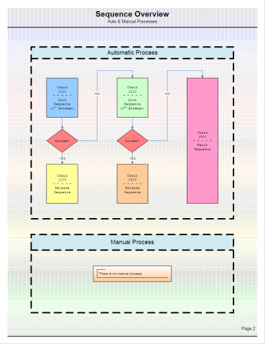
This file is an example showing how the sequence diagram template is used. This file is in .pdf form but is available as a Visio file. Message me through this forum to request a copy. -
View File Sequence Diagram Example This file is an example showing how the sequence diagram template is used. This file is in .pdf form but is available as a Visio file. Message me through this forum to request a copy. Submitter pop29684 Submitted 09/07/16 Category Tutorials and Guides
-
Version 1.0.0
87 downloads
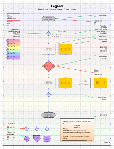
This is a simple sequence diagram format I have developed and used. You may or may not find it to be helpful. This file is in .pdf format but if you message me through this forum I can send you the Visio file. I am offering the Visio file without charge, and without copyright restriction. -
View File Simple Sequence Diagram This is a simple sequence diagram format I have developed and used. You may or may not find it to be helpful. This file is in .pdf format but if you message me through this forum I can send you the Visio file. I am offering the Visio file without charge, and without copyright restriction. Submitter pop29684 Submitted 09/07/16 Category Tutorials and Guides
-
Version 1.0.0
11 downloads
The OMNI Flow Computer driver provides the ability to communicate with the OMNI 3000 and 6000 family of flow computers. It supports both real-time communications and Electronic Flow Measurement (EFM) for historical data. For real-time only communications, the OMNI Flow Computer driver can be purchased individually or as part of theOil and Gas Suite. For applications requiring EFM and real-time communications, the OMNI Flow Computer driver can be purchased as part of the EFM Suite. EFM capabilities include scheduling and exporting EFM History, Alarms, and Events data to industry standard and custom formats. Features - OMNI.Net Client (Master) for communication with OMNI Slaves (Via standard PC serial ports, USB adapters; RTU and ASCII encapsulation in TCP/IP as well as Modbus TCP) - Supports all OMNI devices which uses flavor of OMNI Protocol. - Supports 1,3,5,7,9,11,13,15,17 memory types - Can read up to 128 Words of Input / Holding registers or 2000 Bits of Discrete Coils / Input coils in one transaction. - Performance - 500mhz Pentium - 10 words: 15msecs - 100 words: 35msecs (avg) - Full implementation of Class 0 and Class 1 OMNI protocol functions as well as a subset of the most commonly used Class 2 functions This driver can be conviniently used with Visual Studio in development of complete large scale complex HMI/SCADA Systems. It can be used to perform advanced reporting MES, analytics, IoT, Big data type apps. One example is available to download here For More Info Overview of Parijat Drivers: Click here Additional supporting Info about Parijat Drivers:Click here Complete Related Driver options: Click here -
[Other PLC Demo Software] - Omni Flow Computer Driver for HMI/SCADA
Scadadoctor posted a topic in Download Comments
Omni Flow Computer Driver for HMI/SCADA View File The OMNI Flow Computer driver provides the ability to communicate with the OMNI 3000 and 6000 family of flow computers. It supports both real-time communications and Electronic Flow Measurement (EFM) for historical data. For real-time only communications, the OMNI Flow Computer driver can be purchased individually or as part of theOil and Gas Suite. For applications requiring EFM and real-time communications, the OMNI Flow Computer driver can be purchased as part of the EFM Suite. EFM capabilities include scheduling and exporting EFM History, Alarms, and Events data to industry standard and custom formats. Features - OMNI.Net Client (Master) for communication with OMNI Slaves (Via standard PC serial ports, USB adapters; RTU and ASCII encapsulation in TCP/IP as well as Modbus TCP) - Supports all OMNI devices which uses flavor of OMNI Protocol. - Supports 1,3,5,7,9,11,13,15,17 memory types - Can read up to 128 Words of Input / Holding registers or 2000 Bits of Discrete Coils / Input coils in one transaction. - Performance - 500mhz Pentium - 10 words: 15msecs - 100 words: 35msecs (avg) - Full implementation of Class 0 and Class 1 OMNI protocol functions as well as a subset of the most commonly used Class 2 functions This driver can be conviniently used with Visual Studio in development of complete large scale complex HMI/SCADA Systems. It can be used to perform advanced reporting MES, analytics, IoT, Big data type apps. One example is available to download here For More Info Overview of Parijat Drivers: Click here Additional supporting Info about Parijat Drivers:Click here Complete Related Driver options: Click here Submitter Scadadoctor Submitted 03/10/16 Category Other PLC Demo Software -
Hi everyone. I'm new at Mitsubishi Q series. I can make a connection between PC and PLC through ethernet and read/write from/to registers. When I try to connect second PC to PLC I can't do it and get error. How can I set Network parameters of QJ71E71 module to communicate multiple PCs to PLC? Thanks.
-
Hello Everyone, I am new to ladder logic, and trying to understand flow of below attached ladder logic- How does the program flow ? Does PT4601_I in rung 3 waits for rung 2 to complete inorder to consider updated value of PT4601_I or it consider PT4601_I default value and runs simultaneously with rung 2 ? Thank you in advacne
-
Hello, I am working on a Siemens S7-300 PLC with a WinCC HMI and I am looking to perform logging of certain values every 12 or 24 hours. Basically I have a Flow meter that constantly has flow through it. Right now I have the PLC set up to record the current value of the flow, as well as a totalizer to indicate how much flow has gone through the valve. (until an operator chooses to reset it) I need to create some sort of logic or utilize something in WinCC to calculate the flow through the valve only for that day. After that day, the value will be either deleted or replaced with a new value the next day... If anyone has any tips or advice it would be greatly appreciated. Thank you,
-
Micrologix 1400 HSC:0 Looking for a configuration example. Using a gas meter with a contact output representing x pulses per cubic foot of gas. Want to calculate flow rate and totalize.