

vanquangtk
MrPLC Member-
Content count
70 -
Joined
-
Last visited
Posts posted by vanquangtk
-
-
20 minutes ago, pturmel said:What does the HMI have to do with this? Comms between PLCs would typically be in the ladder logic of one or both, with various messaging techniques directly between them.
HMI observes some signal of PLC which it controls. Then I will use D-Script function to inform for another HMI (if they can communicate via ethernet)
-
12 minutes ago, IO_Rack said:That is not an Omron product and I haven't used one of those in quite some time. Assuming you want to connect to an Omron PLC (C series, CP/CJ) then you'll need to see if the HMI supports Omron FINS protocol for an Ethernet connection. Connecting multiple HMIs shouldn't be problem as long as each device has a unique IP address. FINS node will be the last octet in the IP address. No PLC setup should be necessary. You'll just need to know the IP / FINS node.
Note, you may see a Host Link protocol available. This is for RS232C/RS422 connections.
I'm sorry for post it in Omron. I can connect PLC with HMI via ethernet. But I alos want to connect those HMI via ethernet (not master -slave relation) so that I can transfer value from PLC to PLC. I search in GP Pro manual, but there are only 2 method: connect one PLC to multiple HMI or connect one HMI to multiple PLC
-
Helllo everyone
I need to connect multiple HMI-GP Pro (each HMI control different PLC) via ethernet.
May anyone show me how to set up the connection, please.
-
19 hours ago, nehpets said:The time base is dependant on the timer number,
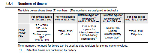
Thanks, but I want to create a TIMER_VAR not a fix address timer.
-
6 minutes ago, Crossbow said:It would really help if you indicate which family of PLC you are using, as there are some differences.
I use FX3U PLC.
-
Hello everyone,
I'm looking to use a timer with a 10ms interval in a function block. However, I'm unsure about how to create it, as all the timers I've declared so far are set to 100ms. Could someone please provide assistance?
Thank you.
-
3 hours ago, pturmel said:And how can a PID controller do that?
This is code I wrote to do that
-
2 hours ago, pturmel said:Using a PID controller or not has no bearing on the measurement of your process.
I intend to use it to optimize the sampling time in order to ensure both response time and accuracy.
-
Hello all.
I have a problem with RPM measurement for a spindle. I hope someone can help me.
My company's machine uses a disk with two pinholes to measure the speed.In the current program, it uses the following instruction to measure the speed: SPD X0 K3000 D1
The issue is that we only receive 2 pulses per revolution, which requires using a longer sampling time for accurate results. Unfortunately, this leads to a delay in the response time.
I am considering trying a different method for measurement. Would using a PID controller be a good idea?
-
22 hours ago, panic mode said:number of pulses tells how far to move... rate at which pulses are sent controls the speed.
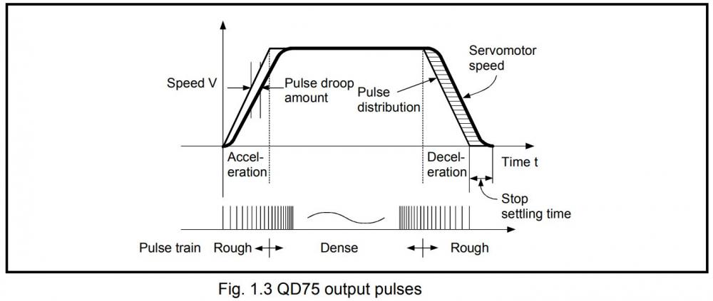
so maximum frequency of the PTO is one of limiting factors. small PLCs often have PTO that only get to few kHz, some may go to 100kHzor 200kH, dedicated modules for larger PLCs are definitely more capable (MHz). by parametrizing drive one can accomplish certain scaling so that for example axis can reach higher speed even when driven by slow PTO. but don't be fooled - this is a tradeoff... you may gain at one end (speed) but you loose at another (resolution). so one need to read the manual, do the math and set parameters correctly to get needed performance. but once you reach point where PTO cannot handle it, it is time to upgrade to more capable PLC.
I still don't understand the role of the "number of pulses" parameter in position control mode. Why is it necessary when the distance varies depending on the position deviation?
In Mr Configurator 2 software, the value of the "number of pulses" parameter is fixed and determined by the value of the electronic gear.
-
21 hours ago, glavanov said:Witch manual?
It is Servo Amplifier Instruction manual MR-J4-A
-
10 hours ago, glavanov said:Number of command input pulses is how many pulses are needed for the servo motor shaft to make one revolution.
So, number of command input pulses does not affect to speed, does it? Do you know what affect to speed of servo in position control mode. I read the manual, but it doesn't mention about it.
-
Hello all,
I don't understand therelationship between of Number of command input pulse and pulse train in positon control mode of Mitsubishi servo.
May anyone explain for me.
-
On 10/5/2021 at 8:45 PM, sczot said:hello,
right click in window with instructions then "Next unmatch"
Thanks @sczotI got it.
-
Hello everyone,
When using compare function in GX Works to search the different between two programs, in the result window I must scroll the mouse to see the difference.
Is there another way to see the diffrence fast and exactly.
-
2 hours ago, AndreasW said:hi vanquangtk,
I think that the positioning jumps to the next point is ok, because this is the basic function of the continous path positioning mode.
If you want to stop the positioning after reaching a point this should be done in the positioning complete mode.So what do you wan't to do with the the m-code signal?
If you want to pause the positioning until the m-code is cleaered you should use positionig complete mode instead of continous path.
If you wan't to detect that each position is reached you can try to immediately reset the m-code with an m-code-off request command
(mabye within an event-interrupt) to detect the m-code of each point, but this will only work if the positioning time between the single
points is long enough.
Thanks @AndreasW, I can't use positioning complete mode because I need the speed keep constant (not return 0 after singgle point positioning completes). Because in Q173D, the speed doesn't return 0 single point positioning completes if I turn on and off the FIN signal soon enough so I want to keep this feature in QD77MS.
-
Hello everyone,
I'm changing a PLC program from using Q173D into QD77MS.
In Q173D, I have a SFC program which uses M codes in 3 point positions. It means after positioning one point, the M code output signal need to be changed from OFF-ON -OFF to jump to the next positon,
I want to keep this feature in QD77MS with continous path positioning mode. But I don't know how to do it.
With continous path positioning mode, if I keep M code output signal on, after positioning one point complete, it will still jump to next point positioning.
May any one help me,please
-
1 hour ago, nehpets said:assuming you mean a timer intergrated circuit a simple well documented unit would be a 555 timer ic, for use with a minimal number of discrete components
I can't set a timer in 555 IC without adding a new circuit. I want an IC which already has a timer.
-
Hello all
I am sorry for posting this question in the forum, because I don't know where is suitable for posting it.
I need an IC that is small, and can set timer in it. I means after setting a timer in it from a trigger, when timer on it will output in pin.
Do you know which IC have that ability.
Thanks so much.
-
Hello all,
Is there any one know how to simulate many controllers at same time in MotoSIM EG-VRC of Yaskawa.
Thanks in advance
-
2 hours ago, Joe E. said:We don't use SE anywhere, but we have a lot of PV+ HMIs, so we use ME. My response is based on using FT View Studio for ME. I can't guarantee that your steps will be the same.
There's a "Global Connections" item in the "System" folder of the project tree. Go to the "Display" tab and there are entries for "Remote Display Number" and "Replace Display Number". Click the "Help" button in that dialog box for information on them.
Also note that you will have to right-click on the background of each display and select "Display Settings" Each display will need a unique display number for this to work the way you want.
Thanks @Joe E., I finally found it. It is exactly what you wrote.
https://www.youtube.com/watch?v=Cf64oco88S8&list=PL7BAkmD1dytiKRUTJTYTGD_uQX7UpbzdW&index=4
-
33 minutes ago, panic mode said:i have not used PLC in recent years but AB allows screen switching just like (if not simpler than) others.
I read the manual "FactoryTalk View Site Edition User's Guide", and I see the only way to switch screen is creating a switching button in HMI screen. But that is not exactly what I want.
-
Hello, I would be really thankful if someone could help me .
Recently, I start using Allen Bradley PLC and HMI. Before, I used most of .I have difficulty in seeking some similar Mitsubishi functions in Allen Bradley.- First, I don't know how to switch HMI screen by using instruction in Allen Bradley PLC.In Mitsubishi PLC, I can do that by move a number to base screen register D0.But I can't find the similar register/tag in Allen Bradley.- Second, I don't know which bit, relay, timer, counter, register will latch it's value when power turn off. In Mitsubishi, I can know that by looking at FX parameter.May anyone give me favour, thanks. -
4 hours ago, Gambit said:There is a FB for a Mitsubishi inverter via MB on the Mitsubishi website
May you give me that link, please.


Connecting to Multiple HMI-GP Pro
in Other Omron Software
Posted
It is interlock signal. I prefer HMI than wiring