

Levent1970
MrPLC Member-
Content count
38 -
Joined
-
Last visited
Posts posted by Levent1970
-
-
Hi Guys,
How can I bring an axis into permanent control? that as soon as a value changes, the axis reacts.
My Hardware FX5U, FX5SSC MR-JE-20B.
Thanks a lot.
-
OK, the Function was Joging but i found the problem, the problem was the other part of my Program, i deleted some functions and it works now.Thanks Gambit!!!
-
Hello Guys,
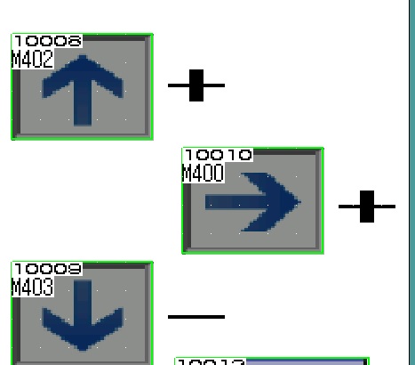
I have a problem with my Screenbuttons, if i push them, my drive moves only an Impulse. I see on the Simple-Motion Module that the Signal is during pushing the screenbutton is active, but the Axis moves only an Impulse. In example M400 is for drive the 2nd Axis to the right side and M405 for the left side.
My Hardware is: FX5U, GOT2000 (GT2505HS-VTBD)
-
Hello Guys,
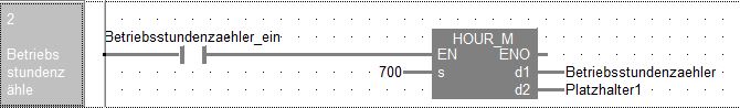
is someone using HOURM as a Retentive Counter ? I Tried it but i have no success.
like this one:
HOURM( Betriebsstundenzaehler_ein , 700, Betriebsstundenzaehler , Platzhalter1 );
I'm using FX5U.
Our old Programm was written in Ladder.
-
If you have on both Modules the MS in Green, your Communication is OK.
My Example:
Open your Communication with the Ethernet-IP Module
FX5ENETIP_1.bSet_CommunicationStartupRequest_D:=TRUE;
Send Words:
U2\G60001:= Value_Current; //My Module is the 2.nd Intelligent Module, use "U1" for 1.st
Send Bits:
U2\G60007.1:= Lamp_Welding;
Receive Words:
Value_Current_from_TP := U2\G12000;
Receive Bits:
bPowder_On_Button:= U2\G12019.2
You can Take in FX5-ENET_IP Users Manual Page 147 the Adresses for Class1 input ( Input starts with Un\G12000 and ends Un\G14999) and Class1 output [ Output from Un\G60000 to Un\G62999)
-
OK it Works, it was a Bit by Initializing :) How can i set a 3rd Position like a "Parkposition" in my List? Its only a Position, which my Axis drives after Start to there and if its done with the Oscillation between Start and Endposition (List Pos. 11 and 12) it drives again to my Parkposition.
-
Thanks Gambit, I started to use the FB s from Mitsubishi, I'm not so Familar with the MC FB, I found out how i can send my Axis to the Position, my problem is, i cant do it again. I have to restart the PLC to drive it once time to this position.
DMOV( TRUE , INT_TO_DINT(Sollgeschwindigkeit_TP_P_Achse) , U1\G7104 ); //Startposition Geschwindigkeit
DMOV( TRUE , INT_TO_DINT(Sollgeschwindigkeit_TP_P_Achse) , U1\G7114 ); //Endposition Geschwindigkeit
DMOV( TRUE , INT_TO_DINT(Sollgeschwindigkeit_TP_P_Achse) , U1\G7084 ); //Parkposition Geschwindigkeit
DMOV( TRUE , REAL_TO_DINT(Parkposition_TP_P_Achse /1.3103) , U1\G7086 );
DMOV( TRUE , REAL_TO_DINT(Startposition_TP_P_Achse/1.3103) , U1\G7106 );
DMOV( TRUE , REAL_TO_DINT(Endposition_TP_P_Achse/1.3103) , U1\G7116 );M_FX5SSC_StartPositioning_Ax2(i_bEN:= Schweissen_ein OR Taster_Schweissen_Ein AND P_Achse_Referenziert ,i_stModule:= FX5SSC_1 ,i_uAxis:= 2 ,i_uStartNo:= 11 ,o_bOK=> StartPosition_OK );
Achse2_InPosition:=U1\G2517.F;
Achse2_InArbeit:=U1\G31501.1;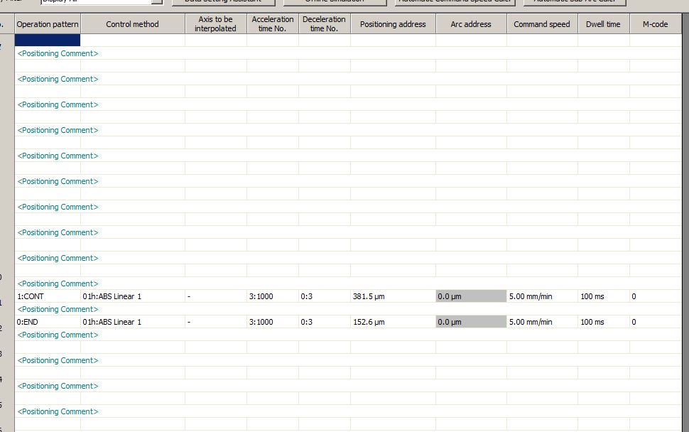
-
Hi Friends.
I need some Help with Positioning. I'm using the FX5U PLC and the FX5-40SSC "Simple" Motion Controller with Servo MR-JE-20B and Servo Motor HG-KN23K which is controlling a Linear Guide.
The JOG Modus is Working, Home Position is Working too, but I cant Programm a Position where the Motor have to Drive. I hope someone can Help.
Part of My Program looks like:
FX5SSC_1.stsysctrl_d.bPLC_Ready_D:=TRUE;
FX5SSC_1.stSysMntr2_D.bReady_D:=TRUE;
M_Ax1_PLC_Ready:=TRUE;
M_Ax2_PLC_Ready:=TRUE;
M_Ax3_PLC_Ready:=TRUE;IF FX5SSC_1.stSysMntr2_D.bReady_D THEN
FX5SSC_1.stSysCtrl_D.bAllAxisServoOn_D:=TRUE;
END_IF;IF M_Ax2_Error_Reset THEN
MOV( bEnable OR PLC_1st_scan , K0 , K4M700 );
M_FX5SSC_OperateError_Ax2 (i_bEN:= TRUE ,i_stModule:= FX5SSC_1 ,i_uAxis:= 2 ,i_bErrReset:= M_Ax2_Error_Reset ,o_bModuleErr=> bEnable ,o_uModuleErrId=> D_Ax2_Operate_Error);
END_IF;IF P_Achse_HomeDrive THEN
M_FX5SSC_StartPositioning_Ax2(i_bEN:= P_Achse_HomeDrive ,i_stModule:= FX5SSC_1 ,i_uAxis:= 2 ,i_uStartNo:= 9001 ,
o_bOK=> bEnable1 ,o_bErr=> bEnable2);
RST( bEnable1 OR bEnable2 , P_Achse_HomeDrive );P_Achse_Referenziert:=TRUE;
RST( TRUE , Referenzfahrt_TP_Ein_Aus );
RST( TRUE , Fehleranzeige_P_Achse_nicht_Ref );
END_IF;
SpeicherP1:= REAL_TO_INT (Startposition_TP_P_Achse);
M_FX5SSC_SetPositioningData_Ax2(i_bEN:= Beginne_FahrtP ,i_stModule:= FX5SSC_1 ,i_uAxis:= 2 ,i_uDataNo:= 1);
M_FX5SSC_StartPositioning_Ax2(i_bEN:= Beginne_FahrtP ,i_stModule:= FX5SSC_1 ,i_uAxis:= 2 ,i_uStartNo:= 1);
M_FX5SSC_ChangeSpeed_Ax2(i_bEN:= Beginne_FahrtP ,i_stModule:= FX5SSC_1 ,i_uAxis:= 2 ,i_udSpeedChangeValue:= 100);
M_FX5SSC_ChangePosition_Ax2(i_bEN:= Beginne_FahrtP ,i_stModule:= FX5SSC_1 ,i_uAxis:= 2 ,i_dTargetNewPosition:= REAL_TO_DINT(Startposition_TP_P_Achse) ,i_udTargetNewSpeed:= INT_TO_DWORD(Fahrgeschwindigkeit_TP_P_Achse));
IF StartPAxis THEN
FX5SSC_1.stnAxCtrl1_D[1].dTargetNewPosition_D:=REAL_TO_DINT(Endposition_TP_P_Achse);
FX5SSC_1.stnAxCtrl2_D[1].uPositioningStart_D:=1;
END_IF; -
Open your Communication with the Ethernet-IP Module
FX5ENETIP_1.bSet_CommunicationStartupRequest_D:=TRUE;
Send Words:
U2\G60001:= Value_Current; //My Module is the 2.nd Intelligent Module, use "U1" for 1.st
Send Bits:
U2\G60007.1:= Lamp_Welding;
Receive Words:
Value_Current_from_TP := U2\G12000;
Receive Bits:
bPowder_On_Button:= U2\G12019.2
Use an EDS file like the attached one in your Ethernet Configuration Tool (See recent Posts from me)
1 person likes this -
On 2.3.2019 at 11:06 AM, Cristian Sulighetean said:I've tried and it works perfectly for about 90% of the times. One thing that I need is to make the program wait for 2 seconds when I activate the vacuum to catch the workpiece .
I thought about verifying that the signal of the sensor that confirms the workpiece is 1 for more than 1 second if it is possible.
Try this:
Local Label:
StartBit Bit VAR
TimerStart TON VAR
OKBit Bit VAR
ProgramBody:
TimerStart(IN:= StartBit ,PT:= t#2s ,Q=> OKBit)
1 person likes this -
On 26.2.2019 at 1:19 PM, Cristian Sulighetean said:Hello everyone,
I am new to Mitsubishi PLC. My device is IQ-F series FX5u-80 and GX Works 3 to set up parameters using ST.
I need to implement a function that waits for a confirmation signal in order to continue to the next step of the program.
I though about another way by using a delay function instead of confirmation single for testing purpose
Why you dont use IF ..... THEN ? like:
IF ConfirmationSignal THEN
NextStep:=TRUE;
ELSE
NextStep:=FALSE;
END_IF;
IF NExtStep THEN
NExtNextStep:=TRUE;
ELSE
NExtNextStep:=FALSE;
END_IF;
-
I Give you here what i found out:
For Open the Communication with the Module:
M_FX5ENETIP_ConnectionOpen_00A_1(i_bEN:= TRUE ,i_stModule:= FX5ENETIP_1 ,i_uConnectionNo:= 1);
To Write WORDs TO the Module
M_FX5ENETIP_Class1SetOutputData_00A_1(i_bEN:= TRUE ,i_stModule:= FX5ENETIP_1 ,i_uConnectionNo:= 1 ,i_uOutputData:= D0 );
To Read WORDs FROM the Module
M_FX5ENETIP_Class1GetInputData_00A_1(i_bEN:= TRUE ,i_stModule:= FX5ENETIP_1 ,i_uConnectionNo:= 2);
To the Robot from the Module:
FX5ENETIP_1.unVal_Class1OutputDataOffset_Connection_D[1] := INT_TO_WORD(EIP_Istwert_Strom);
FX5ENETIP_1.unVal_Class1OutputDataOffset_Connection_D[2] := DINT_TO_WORD(REAL_TO_DINT(EIP_Istwert_Spannung));
FX5ENETIP_1.unVal_Class1OutputDataOffset_Connection_D[3] := INT_TO_WORD(EIP_Errechneter_Sollwert_Pulvermenge);
From the Robot to the Module
EIP_Sollwert_Transferstrom := WORD_TO_INT(FX5ENETIP_1.unVal_Class1InputDataOffset_Connection_D[2]);
EIP_Sollwert_Pulvermenge := WORD_TO_INT(FX5ENETIP_1.unVal_Class1InputDataOffset_Connection_D[3]);
I cant Test it and I need a Solution to Send and Receive my Bit`s with the Robot.
-
Thank you !!! have you a Link for the EDS file of the R30iB ?
-
I got the Parts today, after Update my new FX5U to 1.110, no Errors now. The EthernetIP Configuration Tool have found the ENET/IP Module. Now, how can I Share my In and Outputs over the ENET/IP Module with the Fanuc?
-
They send me (I hope it arrives in the next Days) an FX5U with Firmware Ver. 1.110 or later. It will be Possible with that one. Can you send me an Example, how you Build your Program for Share your In- and Outputs with the Fanuc?
-
I Have to Communicate with a Fanuc Robot Arcmate 100iD, its running ArcTool Software and the Fanuc is the Server. Ethernet/IP is the Recommended Field Bus System of the Customer.
-
My Problem is, I have a FX5U with 1.066, its not running with the E-NET/IP, I Just Ordered one with 17X0001 or Higher Serial Number.
Have you an Example how i can Build my Program to Communicate my Digital IN X1 over EthernetIP ?
-
Hello Guys,
I need some Help to Configure my Program for EthernetIP. I Have to Link my Digital and Analog In-/Outputs to EthernetIP to Control it over a Fanuc Robot.
Has someone do that? Some Ideas?
-
Edited
-
Its on "Data Set Method", I'm Driving with Jog.
The Part of my Programm:
IF Referenzfahrt_TP_Ein_Aus THEN
M_Ax2_Jog_RVS:=TRUE;
END_IF;IF NOT Endschalter_P_Achse_minus THEN
M_Ax2_Jog_RVS:=FALSE;
FX5SSC_1.stnAxCtrl1_D[1].uPositioningStartNo_D:=9003;
FX5SSC_1.stnCmdGenAxCtrl_D[1].uPositioningStartNo_D:=1;
END_IF;HPr Status: StatusAxis2HPR:=FX5SSC_1.stnAxMntr_D[1].uStatus_D; 8 (It's Axis 2)
Pr21 is set 1:Update of Feed Current Value
Pr55 is set 1:Positioning Control is Executed
-
I Found this solution:
ModbusTcpClient(ConnectionNo:= 3 ,LocalPortNo:= 5645 ,RemoteIPAddress:= 16#0A2E6749 ,RemotePortNo:= 502 ,UnitId:= 255 , EnableConnection:= EnableConnection ,StartSend:= StartSend ,FirstAddress1:= FirstAddress ,ResponseTimeout:= 100 ,NoOfRetries:= 1 , SingleDevicesFCode05h06h:= SingleDevices ,ReadOnlyDevicesFCode02h04h:= ReadOnlyDevices ,Read:= Read ,Write:= Write ,BitOrRegister:= BitOrRegister , ReadStartAddress:= ReadStartAddr ,ReadNoOfDevices:= ReadNoOfDevs ,WriteStartAddress:= WriteStartAddr ,WriteNoOfDevices:= WriteNoOfDevs ,WriteData:= WriteData , OpenComplete=> OpenComplete ,CommandCompleted=> CommandCompleted ,ReadData=> ReadData ,ReadDataByteCount=> ReadDataByteCount ,ReadDataWordCount=> ReadDataWordCount , OpenError=> OpenError ,OpenErrorCode=> OpenErrorCode ,Error=> GeneralError ,ResponseTimeoutError=> ResponseTimeoutError ,InvalidCommand=> InvalidCommand , InvalidResponse=> InvalidResponse ,ModbusException=> ModbusException ,ModbusExceptionCode=> ModbusExceptionCode );
Now i can Read and Write something to the MFC Controller, in Example if i send:
WriteData[0].0:=TRUE;
Opens the Valve and a FALSE close this.
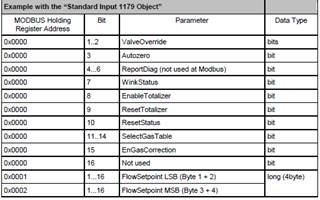
Now my Problem is, I need to set the Flowpoint. How I Can Use 0x0001 Bit 1..16 like below (WriteData[0].0:=TRUE; OR WriteData[0]:=1234)
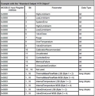
Or Read in Example the ThermalMassFlowRate 0x0001 bit 1..16 (ReadData[1]:=XXXXXX) ?
-
No Luck, its only Blinking between 0 and and the Current Value, if i move it away from this Point the Current Value is still there.
-
I Have a Blackout, U1\G5928 is an INT, how can i set my Digital Input x27 to this INT?
-
In the Selection for the DOG Signal is "Servo Amplifier" or "Buffer Memory" I have No connection on the Servo Amplifier to Connect a DOG Signal (my Limit Switch).
Where can i set my Limit Switch as my DOG Signal or Use the Buffer Memory to say in example Input X27 is my Limit Switch and i want to set it as my DOG Signal.
Axis Permanent Control
in Mitsubishi
Posted
I have to control an analog input, it's about a voltage that is present there. As an example, the axle should go higher as soon as the Voltage is less and lower when it becomes more.