

collinsd70
MrPLC Member-
Content count
264 -
Joined
-
Last visited
Posts posted by collinsd70
-
-
Hi jh07052
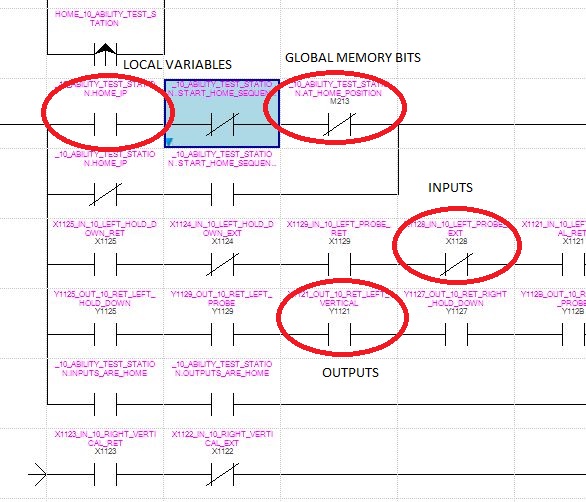
Im a little confused by your question, you want to know why there are no Mitsubishi Addresses on some of these variables, correct?
As I said before, local variables will not have Mitsubishi Addresses, if you dont have Mitsubishi Devices assigned to Global Variables they will be randomly assigned upon compiling.
Regards
Daniel
-
Hi jh07052.
Could it be that these are local variables? (ie in the header).
If they are local variables....they wont necessarily have Mitsubishi Addresses.
I dont know about GXW3...but in IEC you do not necessarily need to declare Mitsubishi Addresses to variables; any not assigned in global memory are randomly assigned upon compiling.
Regards
Daniel
-
Okay, so does the PLC remain on when the power goes out?
Is the PLC ethernet passing through a router or switch?
Regards
Daniel
-
5 hours ago, Lakshmi said:Thanks for your response sir.
How can i set plc tag updation rate in Factory talk view, sir?
In Ftview I have seen screen updation rate only.no option in tag configuration window i think.
This was possible with RSView32.I have seen an option to set scan class for each tag there.
I would look at 2 options...move your tag to a temp which updates on a 1 or 2 second clock pulse or use an AOI for collecting the average every few seconds.
If you want to use a clock pulse; you should collect the WallClockTime in a GSV, if you want to do a average update, I can send you an AOI....
Regards
Daniel
-
Hello Antonio.
Can you expand on your problem, what hardware are you using to establish this connection? Ie Ethernet or RS232?
If you want communication to your PLC at ALL times; you could consider a UPS or possibly a control circuit powered from your incoming side of the isolator. However for the latter; you will need to check the electrical regs for your respectable country first.
Regards
Daniel
-
Could you not just update your motor speed every 1 second from the PLC Tag then keep your HMI settings the same as before?
Regards
Daniel
-
Now you have an Ethernet Driver configured....go to RSWho and select your CPU through the Ethernet Driver then press go online.
Regards
Daniel.
1 person likes this -
I just tested the Unpassive Send and Recieve blocks across 2 Q PLCs and works like a charm, literally took minutes to set up.
Have now encapsulated all logic in FBs with external read in of IP Address and Port numbers and diagnsotics and alarms on Output Parameters (Like 'Link' down and open connection timeout).
All these blocks can be found in the .SUL (library file).
Regards
Daniel.
-
Glad to see you got this working Colin.
Think I might also have a go at this over the weekend, unfortunatley my A-Series only has MELSECNet so will have to test this Q<--->Q.
Ideally id like to nest my core logic in a FB and create some form of communications check. Then port the code as when the necessary projects require it.
Regards
Daniel.
-
Hi Andrew.
Welcome to the forum.
I have not worked on the iQR Series yet, however from what I read; your quickest and easiest method would be to purchase an Ethernet/IP Module for this task- as both Omron and Keyence offer direct compatibility using this protocol.
Having used Keyence laser and barcode hardware with ControlLogix I can vouch that it is very straightforward to use.
Out of interest...why are you using 2 PLCs for your Standard & Safety?, you may be able to map your data between them across a standard ethernet TCP connection; however the actual safety telegrams; you will have to use an approved industrial protocol (such as Profibus/Profisafe or something equivalent).
Regards
Daniel
-
Hi jthyge.
Firstly, welcome to the forum.
If you have entered this as an SCL Source, the compiler will tell you where the errors are when you go to compile.
Dont forget that- you need to declare what type of block you are creating (UDT, FB, FC, DB) with the necessary Symbolic Name. This decleration needs to be at the beginning of your source code.
Regards
Daniel
-
Hi fseipel22
Firstly welcome to the forum.
What about alarms on the ControlLogix? Are you actively monitoring the status of these drives via the entrystatus tag?
If not, it might be worth enabling this so you can track and cross reference your alarms...
Regards
Daniel
-
Okay. Yes I made transition from GX to IEC Developer when I was a maintenance engineer and it really helped. The IEC standards meant Mitsubishi had to allow you access to program writing in the 5 main industrial languages and also encouraged structured programming with the use of Multi-instance FBs.
This type of programming will get you a long way ahead (certainly made my step in Siemens alot easier). If you can adapt your programming methods to this...it allows for easier to understand program flow.
Regards
Daniel.
-
This maybe one of the reasons I still use IEC Developer, for some reason they changed a lot of things in GXWorks2 including a lot of the naming conventions which I find odd (why change something if it works?).
I will have to check this when I am back at my machine.
Regards
Daniel
-
How about Project --> Export?
-
You can right click anything you want....DUT, FB or POU and 'export'.
This saves as an .asc which can then be imported. I find this is the quickest method for importing new code.
Also very useful if you make single changes and want to back up the function rather than the whole program.
Regards
Daniel.
-
24 minutes ago, CJP1967 said:Thanks for taking the time to do that Collins.
The code works well
")
You are very welcome...take the time to understand how it works; for your own benefit :). The nice thing about that FB- is you can use it as many times in your program as you need.
From memory; R registers are 16-bit registers so like your standard D-Registers except they are stored in retentive memory areas. ZR registers are retentive but can be mapped as bits e.g ZR600.1 for example.
They are available as expandable memory on the Q-Series (im not 100% sure on L or iQR series).
Regards
Daniel.
-
Are you able to ping your module from your computer?, have you established the necessary IP address?
You may need to use a ethernet switch if you are not using a crossover cable.
Send me your current GXW2 project and I will integrate the FB for you...
Regards
Daniel.
-
See attached ASCII Source and Image for reading the 5 main error messages from the Modbus TCP Module. I have bench tested this FB but cant test on the real hardware as I dont have this module.
Add this to your project by doing the following.
1. Open your project in GXWorks2.
2. Cick Project --> Open Other Data --> Read ASCII Format File.
3.Point to the .asc file and execute
4.Once import complete, define an instance of the FB in your global variables.
5. Load the FB into your POU and attach instance name, your need to add the head address of the module to the input parameter iHeadAddr.
6. All output error codes will come out as INT's, so either create 5 INTs or just make an array like I did.
7. oNo_Error is a Boolean and is just for indication.
8. Compile and Download then see what errors you get back.
Regards
Daniel.
-
If you can wait until 6pm (GMT) ill send you some code to extract the error informations..
Regards
Daniel.
-
You are using GX Works 2 correct?
Create a connection to function FROM_M in LD..
Connect your module head address to the input parameter (K..head number).
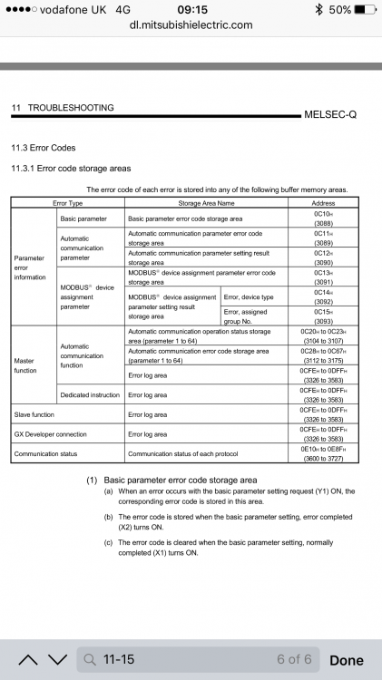
Then your module address area as above, so start with 0C10h.
Connect your output to an INTEGER.
Download and go online....read to me the output parameter.
I do not have my laptop with me at the moment so this is purely by memory.....
Regards
Daniel.
-
Check these memory areas for codes then feedback the error number(s).
Regards
Daniel.
-
For this you will most likely need to extract the error code from the modules buffer memory using FROM_M function.
Otherwise if you have GX Configurator MB- this will give you more detailed error tools.
This is a module specific error and not a direct PLC error which is why it doesnt appear in PLC Diagnostics.
Regards
Daniel.
-
Hi FourFront.
Welcome to the forum.
Yes this is fairly simple- the normal procedure is to change your PLC type in the "controller properties" window, however...you may have to upgrade your firmware dependant on the version your using compared to the processor you select.
Im not 100% sure on your second question- however this may be the portion of processing power dedicated to the communication process (ie MSG instructions, Consumed and Produced Tagging and Ethernet/IP Comms etc).
This link will provide you with firmware compatibility for the L74.
Regards
Daniel

S7-1518
in Siemens
Posted
Hi Nick.
Welcome the forum :).
I have a few initial thoughts.
1. Have you had to flash or update the firmware?
2. When you say you have "formatted" the MMC, how have you done this?
3. Can you establish communications with the PLC?, is so please check for any messages in the diagnostic buffer.
Regards
Daniel