

Filthy McNasty
MrPLC Member-
Content count
77 -
Joined
-
Last visited
Posts posted by Filthy McNasty
-
-
Error 77 is due to an I/O size mismatch between the scanner and the F800.
IF you can determine what the I/O assembly used by the F800 uses, you can edit the I/O structure in the configuration for the F800 in the scanner's configuration setup.
This has to be done without the F800 being mapped.
Remember that DeviceNet makes heavy use of the term 'bytes' when referring to I/O counts & structures.
1 person likes this -
SE comes in different flavors.
Applications can be written for View Site Edition (Network Distributed), View Site Edition (Network Station) and View Site Edition (Local Edition)...which is like an RSView 32 project.
All can be used for their HMI capability but being part of a SCADA system is not mandatory.
1 person likes this -
"Preferred" is a subjective term.
As important as it is to write code for the operation of equipment, so too is writing the code in such a way to make it easy to interpret by someone
other than the code writer if they are responsible to maintain that equipment.
Most of the code I saw in the Sample Code area this morning was not faceplate-related.
1 person likes this -
If you can get your hands on a copy of ICOM or Allen Bradley 6200 software for PLC-2 and run it on a DOS based system, you may be successful.
However, the communication could be dicey as DH/DHII interfaces may be few and far between though there are some legacy communications
converters still floating around.
1 person likes this -
Events have an 'interval' function that allows you to fire an event after a particular interval of time.
INTERVAL("5sec") I think will work. You may have to play with using the quotes or not.
UPDATE: Actually I don't think this will work as I stated above. If I'm not mistaken, Event Detector files run on servers, not clients.
So instead use my other answer I gave you for events on clients and simply use the system\seconds HMI tag to populate a numeric input.
The 'Change' event for the numeric input will foire every second. Just use a MOD 5 function to determine every 5th change.
1 person likes this -
If you have a display that is always present (such as a menu button display), the code can reside there.
Be sure to open the display with the /ZA switch so the code is continuously available and objects capable of changes.
That it will make it available for VBA calls based on an event (such as a tag change).
As in my answer to your other VBA-related question, you can use one or more numeric inputs that have been exposed to VBA to fire the VBA Event code.
If you want to tie it to key combinations, use those key combinations to change the values for the
tags used to raise the events. So you will need to create a 'Client Keys' file for configurating your keyboard combinations.
1 person likes this -
Yes, this is possible.
You can put a numeric input on a portion of the display where it isn't seen (behind something else).You can make it very small as well
as you won't be interacting with it.
If you're going to fire the event based on the value of an HMI or PLC tag, you can put that in the 'Value' field on the 'Connections' tab of the numeric input.
If the value is changed by other VBA code, you can leave the 'Value' field empty.
Next, go into 'Property Panel' for that numeric input and change the 'Expose to VBA' property to 'VBA Control'.
Once that is done, you should be able to right-click on the numeric input and select 'VBA Code...'
That will take you into the VBA Editor and drop you into the 'Change' event code window for the numeric input.
('Change' is one of 9 possible events available for a numeric input.)
Now you add your code.3 people like this -
SE is also used for HMIs
1 person likes this -
In the I/O configuration of each chassis, the RSLogix 500 software will help you to size the minimum power supply required given the current draw of each module in the chassis.
It's only an advisor and will not prevent you from downloading a program to the processor should the power supply be inadequate.
NOTE: This is an offline feature and does not read actual current draw. It uses an embedded database with backplane current draws.
Be sure to size the power supply for future additions to the chassis should there presently be empty slots and to allow for some headroom so the power
supply doesn't run continuously at red line capacity.
2 people like this -
The discrete I/O is easy enough to add back in tot the I/O config.
The analog will require you to add the BTW/BTR files by hand though the module configuration should already be set.
I know of no other way to otherwise repopulate the chassis with the I/O configuration.
However, you could always attempt upload the current processor file into the older project file and unless there has been some I/O module changes (types/positions). you might be able to update the project file with the current setup. You may still have to tweak the I/O configuration a bit. Make sure you have a second copy of that older project file before you try this.
1 person likes this -
You import the file as an "image" and at that point it will be part of the image library and is available.
-
Do you have an example of what you're trying to do perhaps?
1 person likes this -
We do something similar to this in our systems.
The "header" as you call it is an Alarm Banner on a display with 1280x91 dimensions. In the display properties it is set to to load at position 0,0. (More on that later.) The "Title Bar" option is set to off. It is configured as an "On Top" type of display.
The "footer" is a menu bar that uses a 3x8 arrangement of buttons in a hierarchy with captions and commands determined by upper level choices.
The menu bar is on a display with 1280x100 dimensions. It is loaded at startup with a parameter file that sets initial captions and VBA takes care of changes to captions. It is configured to load at position 0,0. (More on that later.) The "Title Bar" option is set to off. It is configured as an "On Top" type of display.
The body or "Master Picture" area is set up with 1280x896 dimensions and is set to load at position 0,0. (More on that later.) This display (and others like it) are set as "Replace" types of displays. These are the displays our operators do 90% of their work. he "Title Bar" option is set to off.
When we run a client session, the startup macro looks like this...macro commands in bold. Omit double quotes.
Display "header file name here" /DT Because we are docking it at the top (/DT), the 0,0 position in the display settings for that display
setting is ignored. (It's actually redundant)
Display "Master Picture file name here" Because we docked the header file display and the display settings for your Master Picture
display are set to load at 0,0 the system will determine that as far as the Master Picture display
is concerned, 0,0 is the lower left corner for the header display.
Accordingly, it will load your Master Picture display directly below the header display.
Display "footer file name here" /DB We load this last because it will dock itself at the bottom of the display (thus ignoring its 0,0 position setting
in the configuration settings for the display.
The result is two displays of equal width and minimal height sandwiching a larger display of equal width but considerably more height.
None of the three displays shows a Title Bar at runtime.
Attached is a screen shot of the menu buttons (similar to your "footer")

-
3 hours ago, kaiser_will said:A typical method is to use a 60 sec timer and a one-shot to a counter for seconds; test seconds = 60 then increment another counter to get minutes; test minutes = 60 then increment another counter to get hours. Add in the ability to reset and add tests to make sure you do not keep counting and fault your processor.
You won't fault the SLC with a counter rollover. Though the negative accumulator will make for some strange display numbers
1 person likes this -
You won't see a change in the priority in the property box. The scan is too fast....also...
The UID doesn't raise the priority of the task that it is in, it merely prevents any interruption of the task until the UIE or (in the case of ladder logic), the last rung of the routine that the UID is in gets executed. In other words, that last rung is an implied UIE.
One task that CAN and WILL interrupt all tasks (even if a UIE is in effect) is the Fault Routine (if configured).
As far as I know, condition(s) can be placed in front of the UID.
-
When working With FIFOs, I execute the FFU before the FFL.
-
On 12/12/2016 at 5:27 PM, Gerry said:I wonder if there's any difference in scan time using individual BOOL tags vs. aliasing them to bits in a DINT.
It's definitely wasteful of memory.
I believe the physical location of the memory used for the base tag & any aliases to it, is determined during the compile phase. If it is, there is no resolution needed during the scan so I don't think scan time would be affected.
The question of individual bits vs. alias to DINT members comes down to what you're using the BOOL's for. If it is total isolation (such as ONS instructions) vs. situations when you m,ay want to be able to affect more than one of the BOOLs.
While an individual BOOL does scrap the remaining 31 bits of the DINT required to allocate space for the BOOL, I don't think the memory wasted would be a big concern given how much memory are in the controllers these days.
-
You do have to be online.
You have to start an edit after the initial browse.
Make sure the modules are NOT inhibited before you schedule your network.
Adding these new I/O modules will require that the L61 be placed in Program/Remote Program before the scheduling can take place.
Remember to check to see that the UMAX is set to a valid node number.
-
Those in the diagram are mostly nested branches and a couple of parallel branches.
That rung will take longer to scan than if the outputs would have been made parallel branches instead of nested branches.
Scan time can be further reduced by putting the outputs in series. Another advantage of putting the outputs in series
is that you won't crowd out the screen with that rung. It may allow 2 or 3 adjacent rungs to be displayed thus minimizing the need to scroll up/down as much.
-
That's FT View SE. The OP was asking about RSLogix5000
To my knowledge, RA has not opened up the API/Object Model for RSLogix/Studio 5000.
-
Constants can't be used. Create an HMI tag and assign its value to the constant you need.
Then you can reference the HMI tag.
-
An SQO instruction driven by 3 timers would work.
1 timer for your dit length
1 timer for your dah length
1 timer for inter-character/inter-word spacing.
-
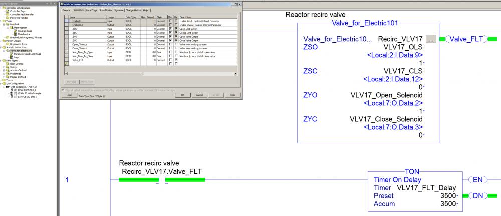
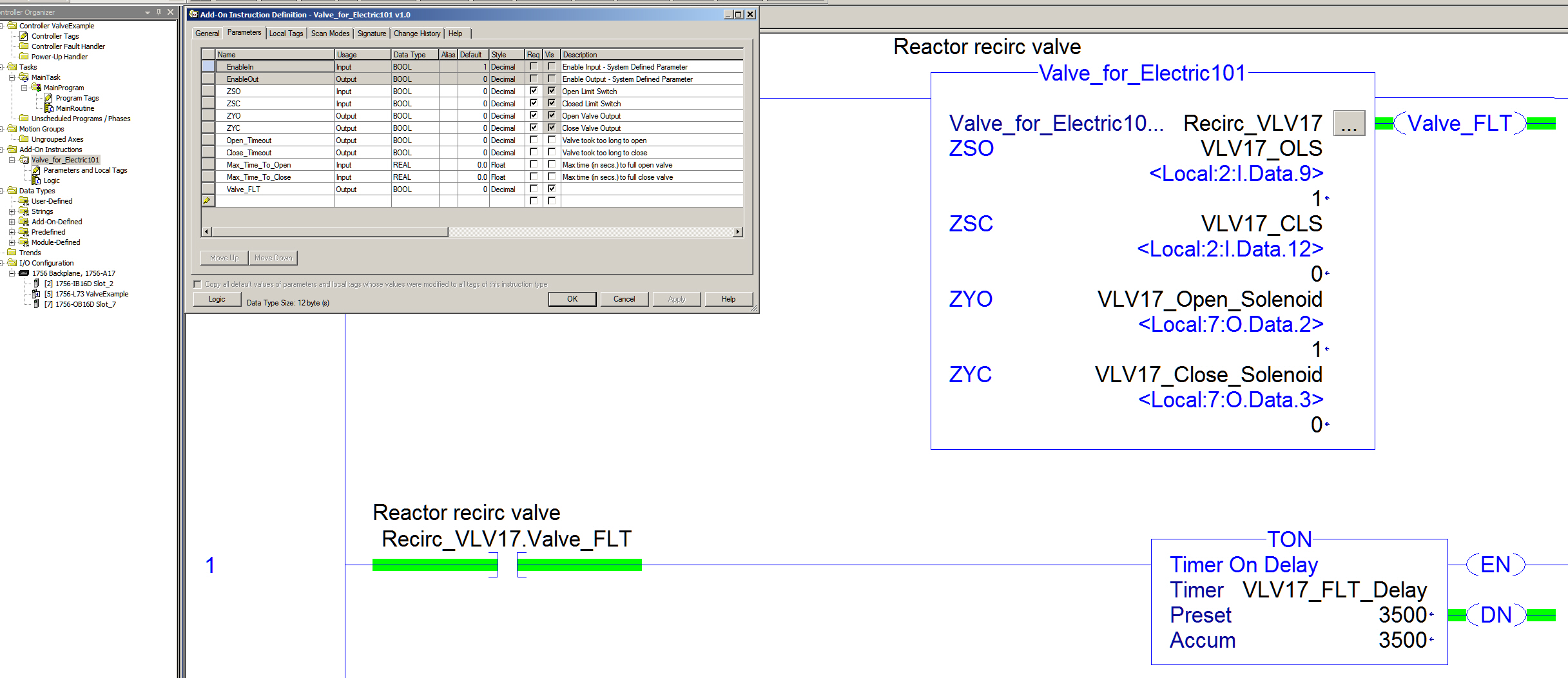
I would simply create an AOI and use Input Parameters for ZSO, ZSC, and Output Parameters for ZYO and ZYC.
Maybe also include Input Parameters for Max. Time to Open, Max. Time to Close, Valve Fault Reset. An Output Parameter to show Fault (Max. time exceeded)In effect it is like creating a UDT however it's actually an Add-On-Defined Data Type and can be reused as many times as needed.

High Pass / Low Pass Filter Knowledge
in Control Panel Building
Posted
How so?