

Dave W.
MrPLC Member-
Content count
27 -
Joined
-
Last visited
Posts posted by Dave W.
-
-
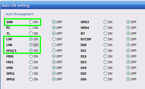
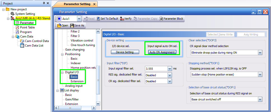
I know, I'm late. But maybe it will help in the future.
You can also set all hardware inputs in this dialog.
This is helpul for "servo-on" and position limits to.
-
Hello
I'm not sure if I understand your question correctly.
If you measure the resistances while the encoder is connected and supplied with voltage, then no reasonable value can be measured.
If the encoder is connected but not supplied with voltage, it can also be the encoder that leads to these measurements. Depending on whether track A or track B or both or neither is active, this could lead to different resistance values.BR, Dave
2 people like this -
Hi,
If the torque limits should be fixed, the parameters PA11/12 can be used.
If the limit is reached, the TLC output is set.
However, the torque limit could also be set via an analogue input.
You can find all the information in the MR-J4-A manual: External LinkI wish you success
Dave -
On 17.3.2022 at 10:10 PM, Crossbow said:I don't think so. I think the barcode function was only for the RS232 serial port. But have not touched on in years, so can't say for certain.
I think the USB ports are for keyboard, mouse, flash drive only...
Sorry late, USB barcode scanner works fine with GOT 2000 at least with GT25 / GT27
-
Same with GX Works3 or use "Cross Reference"
1 person likes this -
R64P is the power supply.
")
OK, I'm late but I've already taken this screenshot. Maybe it helps someone else.
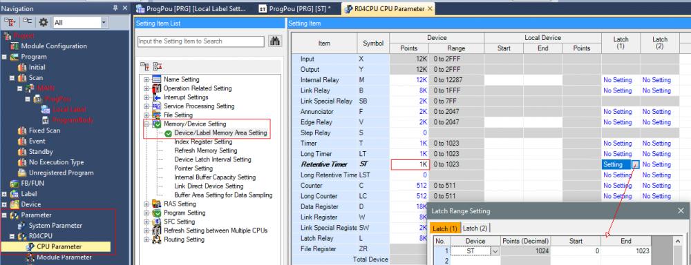
Dave
-
On 13.9.2022 at 4:18 PM, dialgutagm19 said:Hi Dave.
thanks for your help, the problem is that I don't understand how Modbus TCP-IP (slave) works, for example, I'm sending some registers D1 until D34 but when I checked it on the Modbus pull it says (read error, write error), I don't know why it happened if I'm sending the wrong type of data or is something different.
and also y need to receive some data from a master that is allocated in the Modbus direction 42000 - 42059 so I don't know how to set up it, if I only need to use D42000 to D42059, or how I can direct that data to a usable variable, I'm kind of confused
Just to clarify, with Modbus the slave is called the server. This never sends anything on its own.
The client (master) reads and writes data provided by the server.
Here is an example in which the holding registers 40000..40033 are mapped to the device D1..D34. Also register 42000..42059 to D100..D159.
A client can than write and read only in these areas. You can configure this freely according to your needs.For testing I always use the tool QmodMaster a free master for MB-TCP and RTU
Dave
Settings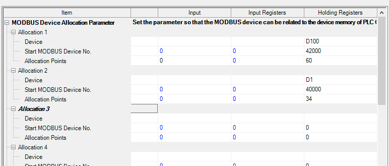
Test:
One important thing: the slave ID / slave address must be 255. (See screenshot) This could be your problem.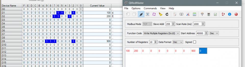 2 people like this
 -
16 hours ago, dialgutagm19 said:Hi everyone someone can explain to me how to use Modbus TCP IP as a slave in a Mitsubishi fx5u ??
I'm not sure how to start it and the manual is confusing me cuss there are too many ways to config it.
For a step by step solution for MB-TCP Server (Slave):
- Download the manual JY997D56101 to e-manual viewer.
- Put this site-ID in the search field of the "e-maual viewer" and select PAGE in Filter section. JY997D56101-BF
If you don't change anything in the settings here: JY997D56101-C3.P2, all registers of the PLC are available on Modbus.
If this is not what you want, delete the unwanted registers there:If that doesn't help you, describe your problem in more detail.
Dave1 person likes this -
Hi
I think the option module FR-A7AN give you two more analog outputs. (4..20 mA)
There may be other modules as wellGreetings
Dave -
I don't speak ladder but in ST I would do it like this.
Maybe that helps.Greetings
DaveP.S. If you need INT not REAL (with one decimal place) you can add this at the end.
nResult := REAL_TO_INT(rResult * 10.0);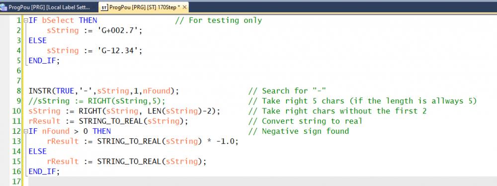
-
Hi DavidOtt
I have made tests with this Node for Node Red.
works find with FX5U.
Maybe you can read the code behind this Node?node-red-contrib-mcprotocol (node) - Node-RED (nodered.org)
I wish you success
Dave -
On 17.9.2021 at 10:44 AM, DWIM said:Ahh...Country representation people = Dave W.

Yes, I work for Omni Ray AG which is the representative of Mitsubishi Electric Factory Automation in Switzerland.
Unfortunately, I'm more likely to get help here than at the European headquarters.
And you?
-
On 17.9.2021 at 7:57 AM, DWIM said:Hi, the PLC has a cycle time of at least 25ms. With 25ms you are a happy chap! We have here on large Programs cycle times of up to 125ms and if we poll multiple devices we have reaction times of seconds!! We asked the country representation people. It is normal....
There is nothing fast with PLC and Mitsubishi. But probably all PLC's suffer from this. It is the Cycle time of the PLC.
If anyone knows a setup with Mitsubishi to read/write 6 Bits (!! yes bits !!!) to 30 external devices in under one second...I have open ears.
And this in the age of 100Mb mobile connections.......Shannon and Moore are facepalming in their graves.Hi DWIM
Thanks for your answer.
My L-CPU doesn't have much to do. Cycle time approx. 2.5ms. It's more of a problem with the predefined protocol.I made communication with many stations with FX5U and Ethernet / IP - Module. With 30 slaves from Moxa (ioLogik E1214) Unfortunately I can't remember the total transmission time.
Really fast communication is possible with iQ-R and CCLINK IE Field, but it is very expensive.
-
Hello, everyone
I have to query a SICK distance sensor from an L26CPU via the onboard Ethernet interface.I have created a simple protocol which I start with the function block SP_ECPRTCL. Unfortunately it takes at least 25ms until the next telegram is started. The sensor responds within approx. 1.5ms. Does anyone know whether that works faster or is that a limitation when using the predefined protocols?
Sensor manual: OD5000, 8021391 (sick.com) (Chapter 7.4)
I am grateful for all the hints.
Thanks and regards
Dave -
Thank you, good suggestion.
I just have to find out how it works.
I never use ladder certainly not inline ST .. -
Hi there
I have to use simple ladder in GX Works 2 with System-Q.
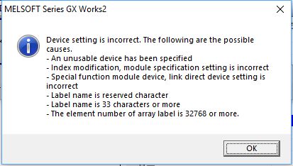
I need to handle a two dimensional array.
That seems not to work because I became a Error message. (Screenshot)abTest[1] works, abTest2[1,2] doesn't
In ST everything works fine.
Thank you in advance
-
What do you mean by your message?
With the newer Firmware for FX5U, Modbus-TCP Server is natively available.
To download the demo project above, you have to be registered on this site.
-
Update: Modbus-TCP Server functionality is now possible without any FB. (Firmware 1.60 an above).
All the necessary settings are now located in the parameter section.
-
Finally it works great!
FX3U Read / Write D-Register from Slave FX3GE.
-
Hi Gambit
Can you give me a name of the library, because I don't find anything suitable.
I have found: " FX Series - GX Works2 - Ethernet - EthernetFX3FixedBuffer_GW2_V101 " but I think that's not the right way.
In this moment I found "EthernetFX3MC_GW2_V100" maybe it is what I need. I will inform you here.
-
Hello everybody.
I am looking for a solution for an FX3U with mounted FX3U-ENET on the right, to communicate with an FX3GE.
I need to read and write some device in the FX3GE from the FX3U.I have made a paired connection in the FX3U-ENET module and made an MC connection in the FX3G.
But how can I send or read data? Is there another solution apart from the MC-Protocoll?
I am using GXW2 version 1.551z. Languages: ST or FBDThank you in advance
Dave
-
Which CPU do you use?
With L-series or System-Q with SD card, you can set up a logging and save as CSV on the SD card.
With the FTP server on the CPU switched on, an FTP client should then be able to be fetch the file.
I have never tried this and therefore I don't know how to access the SD card via FTP . But this solution would be free
-
I have a solution from Mitsubishi.
It looks like the on board Ethernet is compatible with System-Q and L-Series. In the attachment you find a demo project for GX Works3 which is based on the library "LQnUDEModbusTCP_GW2_V110". This project works fine with my FX5U. So Modbus-TCP server and client is possible with FX5U without big effort.
9 people like this -
Thanks for your fast reply.
The FX3U is too old-fashioned for me.
Do you know whether the FX3U-ENET P502 works together with the FX5U?
There should be an adapter for using with the old modules, as far as I know. The new, fast bus becomes then obsolete but nevertheless ..
Dave


Axis ON Problem
in Mitsubishi
Posted
I have already used this module and the function blocks.
However, only the function blocks in the POU “Axis_1_Manager” and only with MR-J4-B.
But it should also work with MR-JE.
I would delete the other POU's.
What does the Axis monitor say about the axis?
Attached is a demo project for FX5-40SSC and MR-J4. I made some FB myself.
FX5U_4SSC_MRJ4_ORAG_Demo_v0.4.gx3