
panic mode
MrPLC Admin-
Content count
3018 -
Joined
-
Last visited
Posts posted by panic mode
-
-
and of course there are tutorials and examples. feel free to use google.
example:
-
-
you need to define what is that you really need, stop moving the goal posts. first you wanted an integer, then floating point, then fixed point.
what are you using value for?
if it is display, then integer is fine. you can specify decimal place by formatting your HMI object
if you are looking at value to control the process, floating point (95.000002) is fine
but floating point values (real type) cannot accurately represent any number.... there is going to be rounding.
so the other option is to keep it in string format...
what is it going to be?
-
so you start with 9950, and get 99.50... isn't that what you wanted?
-
your rDiv is 0.01 which is 1/10^2
so you need to multiply by rDiv, not divide.

...or the rDiv need to be 10^2 instead of 10^-2
-
exactly... those byte values are ASCII characters.
1 person likes this -
MyInt = 0
MyInt = MyInt * 10 + (sHPA[0] - 48 )
MyInt = MyInt * 10 + (sHPA[1] - 48 )
MyInt = MyInt * 10 + (sHPA[2] - 48 )
MyInt = MyInt * 10 + (sHPA[3] - 48 )or
MyInt = (sHPA[0] - 48 )
MyInt = MyInt * 10 + (sHPA[1] - 48 )
MyInt = MyInt * 10 + (sHPA[2] - 48 )
MyInt = MyInt * 10 + (sHPA[3] - 48 )48 is decimal value for 0x30
-
that is sad... many devices default to 9600 but could be convinced to change default to something else. i am doing this right now with some RFID readers.
-
it is just like any other PLC. programming software resides on a development station (your laptop). you simply deploy project to a target PLC which has own firmware and license.
if you do not have physical PLC and wish to learn how to use TwinCat, you can use local runtime. it is an equivalent of a PLC but runs on your own machine. it too needs license but for local runtime, you simply create new temporary license yourself whenever needed.
-
have not used it but according to Omron, you do not add reference....
after installation of Compolet, you should have the control show up in the ToolBox (at the bottom of the list) and you need to drag it onto your form... the same way you would use timer or button or textbox:
https://www.ia.omron.com/data_pdf/cat/cx-compolet_v302-e1_13_5_csm1000258.pdf?id=63
-
is that really the only rate it supports? i would check with manufacturer if there is command to change the baud rate.
another possibility is to split the network into two or more smaller ones. the fewer nodes are polled, the quicker the update.
-
the key problem here is very low baud rate. crank that to 115.2kbps or even 230.4kbps and you will get 10x or 20x higher performance.
another thing to consider is the actual process values. temperature changes are slow but pressure changes can be very fast. you could modify your code to read temperatures less frequently (say 10x less frequent). that could give you further bust.
-
hmm... that sounds awfully slow... what hardware? are you using Ethernet or serial? if serial what baud rate and how many registers we are talking about?
for performance it would be prudent to map all the monitored data into consecutive registers and read them all at once. also it would be good to make sure your target device is able to deal with the required transfer rates.
in couple of recent projects i was using Ethernet to continuously read some 80 registers and write another 30. I chose to update every 100ms but as i recall ratcheting this to 10ms was not an problem at all.
-
i am not aware of direct replacement but one can compose data in a number of different ways. one of them is to use mask and shift instructions. for more convoluted arrangements it is probably easier and more readable to simply pack things bit by bit using contacts and coils.
MOV D4 K4M0 ; copy 16 bits from D4 to M0..M15
then use LD/OUT to remap the M bits to some other place (M100..M115 for example) with order you like
and move it back using
MOV K4M100 D5
depending on particular CPU version other options may also exist.
and if you like, just make own function that duplicates BTD exactly
-
is there an installation log perhaps? sounds like something went wrong...
-
maybe so but your software is trying to connect to a real PLC and obviously fails.
-
i have twincat3 running on my current machine. personally i love freedom and plethora of programming options this system offers. just for learning one can simply download and install TwinCat3, without getting PLC or iPC because it comes with runtime. however if you can, it is always better to get the real hardware.
as for messing things up, things got better over the years but there are still glitches. one of the problems is that using shared CPU core for runtime is likely to conflict with any other virtualization platform (vmware, virtual box...). workaround is to assign dedicated CPU core to runtime. your Windows will have one less core but this tends to solve some of the conflicts (but not all). i use bunch of VMs for other things and... usually couple of them are running. Since TwinCat is installed on this machine, i still get occasional crash. In worst case PC got locked up and all one can do is hold power button to force shutdown. Did not get that since assigning one of CPU cores to RT. also i try to stop RT when not in use.
1 person likes this -
as always, read the relevant documentation, make necessary connections and configuration, then write program to send the value.
if you run into trouble post your work and ask for help
-
if you do want to write words (MW...) and set/reset single bit you need to manipulate the bit in the word and then write entire word.
if you want to ensure there is no corruption, you should first read the word, manipulate the bit of interest, then write the word back.
but first of all let's make things clear - you should not use same register for R/W access as this is too long and complicated (read>manipulate>write back) and there is always a chance of getting things out of sync. this is because value that you read could be out of date by the time you write new value back, some of bits could already be modified (in the PLC) so your write back attempt would overwrite them and thus create corruption.
it is a MUCH better approach to simply choose a range of memory locations (such as register) that you only read and choose another range that you only write. once the value is transferred, you may evaluate it at received end - no need to write back.
that is of course if you want to reduce your communication to single read and single write...
but if you do not wish to parse received data, then instead of reading just one range of memory locations (such as registers), read two or three or more... one could be bits/coils, another could be bytes, another could be words...
same goes for writing values back to PLC. instead of writing one range of memory locations, just use two or more writes. again, one could be some range or bits/coils, another could be bytes, another could be words...
-
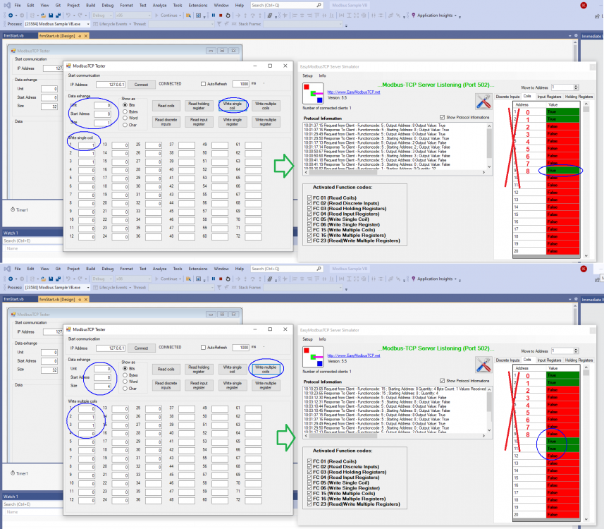
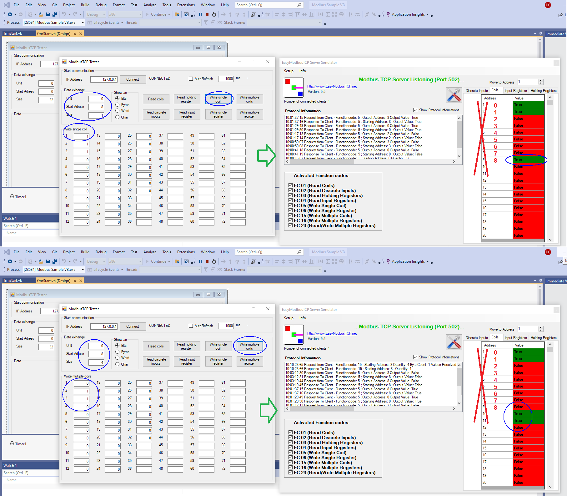
well solution is to use all resources at your disposal that Easymodbus offers. and it has plenty...
on the right side is EasyModbusTCP Server Simulator. it is a great substitute for PLC when doing testing.
on the left side is corresponding client which has ability to read/write anything including single coils...
so, all you need to do is try it and look inside the code how things work.
-
indeed...
one may also just try to create another account using different email . last time i had TechConnect was 20 years ago but clearly using private email and new account did get me through.
-
-
1 hour ago, Zamora said:The QD77MS4 Module is mounted in Base Slot #3, so I use U2\G800, U2\G1500, etc... to Read/Write from it.
so why do you think that U2\xxx should work? and what was the U?\... you tried when module was in slot 1?
that number "2" in U2 is not a 'slot number'... it is a base address which is begin of I/O address for that slot.
what are the modules in slots before Slot#2? depending on how much I/O they consume will determine base address of next module.
if you put the module next to CPU, base address should be 0, so U0\G800 etc.
suppose slot1 is a card with 32inputs. thay means they will be X0...X1F
so next slot (slot2) will start with X20. if module there is 16inputs, they will be X20..X2F.
then next module (slot 3) will start with X30.
base address is obtained by removing "X" and the last digit. so in this case module in slot 3 would have base address 3 ("X0030" after removing X and last 0 becomes 003 or just 3). so you would need to use U3\G800 instead of U2\G800.
if module in slot 5 uses inputs X0320..X033F then base address would be 032 and not 4
1 person likes this -
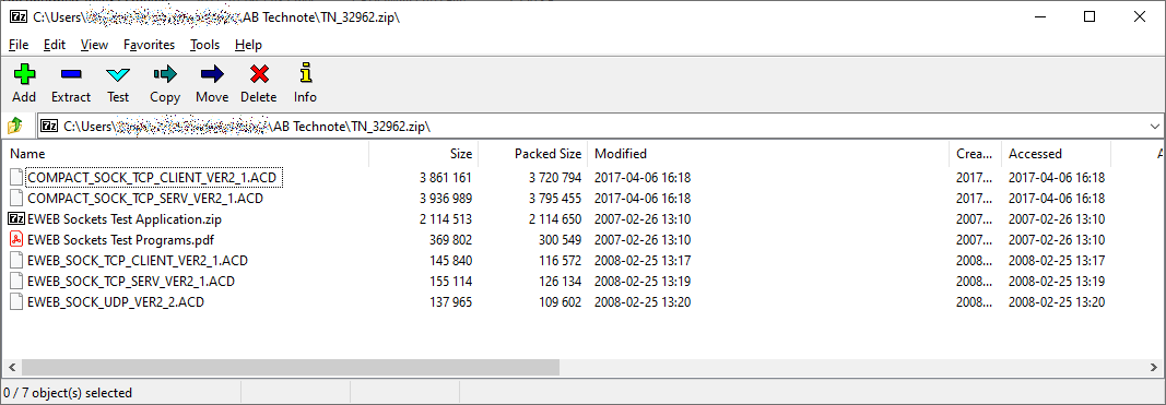
i tried to login using old yahoo email ("forgot password...") and got notified that account does not exist.
so i registered new account and with this i was able to access it as well as download linked manuals, plc code as well as related tech note.

Hardwired PLC to Wireless via bridge?
in Siemens
Posted
KUKA KMP/KMR use wireless Siemens Scalance and not just for Siemens PLC. it can be configured with different options. There is a lot of options and even more settings...