
panic mode
MrPLC Admin-
Content count
3016 -
Joined
-
Last visited
Posts posted by panic mode
-
-
no but any general purpose or signal diode will do. you can literally replace it with very common 1N4148 or 1N914 or if none are at hand, the classic 1N4001 .. 1N4007 (a huge overkill and larger in size).
1 person likes this -
very good. it is always better when manufacturers offer support for their products.
 1 person likes this
 -
On 4/8/2022 at 11:41 AM, BobLfoot said:The "freexe" number just happens to be greater than or equal to 2^28 in all four cases. And before anyone asks, yes the task is periodic and scanning.
makes sense... 32-bit reals use only 23-bits for significant (remaining 9 bits are used for sign and exponent). so they are only good for about 7 significant figures when viewed in decimal... which is why 268455840 or 268455847 makes no difference, both get rounded to a same value.
-
you are in business of building electrical panels but you don't know if and what standards are met is an indication that you are not qualified or authorized to do that.
https://control-works.com/ul-508a-control-panels-basics-and-benefits/
in that case you can still build it yourself but get your local field evaluation inspector to check it out and apply correct label. if he finds that something is not ok, you will need to fix it and have him come again. hence, i would suggest to talk to him before you start building to avoid any issues later on.
or just get some certified panel shop build it for you.
-
You can try contacting manufacturer to give you modified ESI file that does not use or mention that feature or has it turned off.
Or you can replace PLC for one that does implement this EtherCat feature. EtherCat is developed/supported/popularized by Beckhoff so their PLC will likely have no problem with this. Other companies may support EtherCat but only implement subset of features that EtherCat actually supports.
You can also contact Omron and ask about possible way to resolve this. If things go well, it may be just software patch with or without PLC firmware upgrade.
-
14 hours ago, mmd604 said:I am curious I have a question I was looking at a program and the inputs and outputs each had theyre own subroutine and the input subroutine had the inputs on one subroutine connected to a alias tag and then the outputs had the same the alias connected to the outputs. What is the benefit if any to doing this?
mapping I/O to intermediate data set adds to code length and consumes more memory but it also allows several possible advantages even on a single thread PLC. here are some ideas worth considering:
1. Imagine world where things are done by teams. you are doing programming (and maybe working remotely) and someone else is doing panel wiring. so you may not have access to the real hardware or maybe you only have the PLC CPU but not rest of the I/O or fieldbus etc. then you can still easily write your code without consideration of the IO architecture, type or order of I/O modules etc. the mapping to physical I/O is simple step that can be done later on to work on whatever hardware is actually used.
2. signal names can be more descriptive or easier to use.
3. Imagine one of PLC inputs or outputs is failing and you do not have a replacement module at hand but there is a spare (unused) input or output point. of course you can move the I/O wire to that spare I/O point and make change in code. but if the address of that signal is used in 50 places in program, you would need to search and replace it in 50 places. this can be time consuming, error prone, and makes revisions/program comparisons more difficult. but if you are using intermediate variable, you just need to make program change in one one place. guess which option is preferable when production team is breathing down your neck? And what if this change only need to be temporary and will need to revert back but - you are still developing/testing and making other changes in your PLC programs? reverting things in one place is easy but comparison or in depth search/replace can be very time consuming and error prone.
4. Imagine if one of the signals needs some conditioning (delay, inversion, debouncing, etc.). if that was a hardcoded I/O address used in 50 places in your program, you would have real mess on your hands.
5. your code is a certain "black box" of certain functionality. you spend time developing and debugging it... imagine client decides that they already have plenty powerful PLC that controls entire plant and that same PLC will be used to run several of your "black boxes", you will just need to use different I/O, some of the I/O is local, some is remote. if your code is not using hardcoded I/O addresses, it is easy to create multiple instances of it and complete the task in no time.
etc.
-
Hook up few buttons and lights and off you go. Getting familiar with wiring is an essential step as this will be indispensable skill when troubleshooting and commissioning real project. If you have doubts about something, share what you are planning to do what the concern is. that is the best way to get feedback. starting point is always getting access to correct documentation and reading it, specially when doing something with hardware like wiring mistake here can damage things.
once you have some tester ready - rest of the experience is programming and that will take some practicing... Just be patient, things get time...
As with anything, try out common constructs, see what the behavior is not just in run time but also after reboot. A good example of that subtle difference is easily observed in seal-in vs latch/unlatch. once you have something working, it is not game over. you really want to mess with it and try different things to see how it behaves after you change this or that. before every change set your expectations and make prediction what the outcome will be. then do it and see if you were right. also ask yourself how can you accomplish same using different approach or instruction. this will prepare you to transplant your code to a platform that does not have specific instruction.
There are countless more examples but once you have handful of code snippets, you can always use them. basically all programs are combination of frequently used pieces of code. very few things are really something new.
some very common and things are
start/stop logic
signal conditioning (debouncing, edge detection...)
watchdog timers
sequential logic (any way you like)
data manipulation (encoding/decoding values, scaling...)
-
hmmm... i do not know if that is possible.
sure one can create object and run some code when that object is interacted with ... but ... that is different from running something continuously.
pretty sure that would require creating stand alone application.
-
Moxa is not a product and certainly not a specific one. It is a company that makes many products and it is unclear which one you are trying to replace.
How many ports? What specs and type of serial? RS232, RS485, isolated or not, what speed etc?
I've just used couple of different products with one or two ports from USRIOT. They are low cost and seem to be working rather nicely and have plenty of features. Also they are literally everywhere so no problem sourcing them quickly. The one i used the most recently is USR-TCP232-410s which can be powered by 24V too (5-36V), or with own PSU. It has both RS232 and RS485 which can be used simultaneously. They also have VCOM software and program examples if you need direct access without VCOM software.
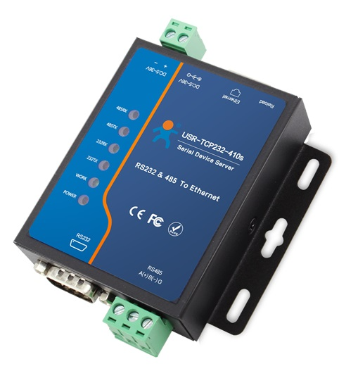
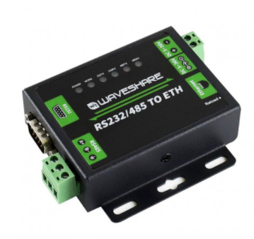
Btw. Plenty of other products on the market are actually rebranded USR products, for example Waveshare is just one of several and as such can use same VCOM software. In fact the program examples, and most of the support files are straight from USR.
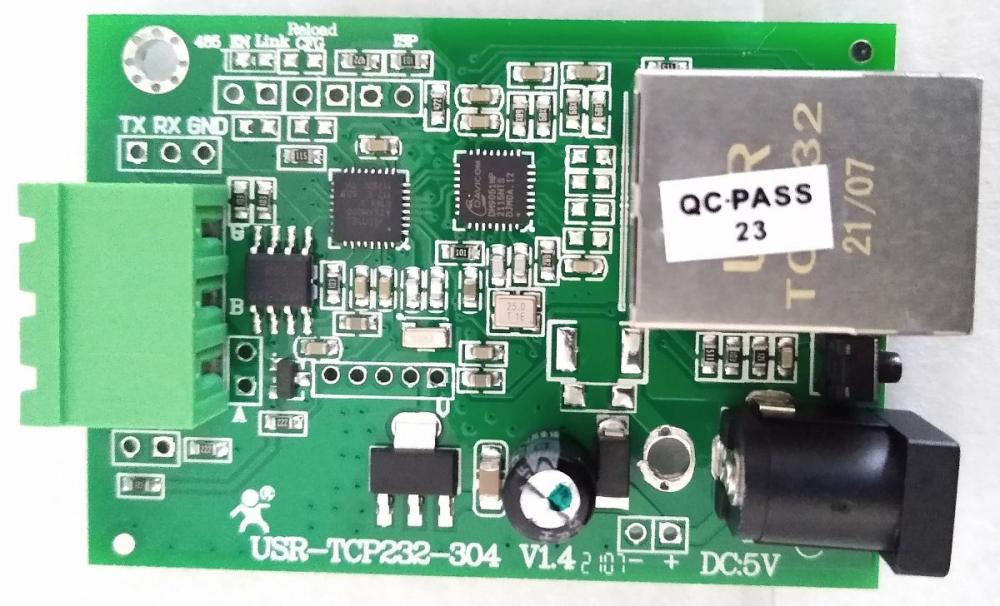
Even if you open one of them and look inside
you will find the USR part number and icon:
-
UK has own electrical code and if installation is in UK, that is the code to be followed.
This seem to be it:
-
%I should be Mitsubishi X
%Q should be Mitsubishi Y
%TM should be Mitsubishi T
-
btw my personal favorite is to log events into a database. then you can get anything you want using simple query. obviously implementing comparable functionality in limited PLC memory will require some careful planning and this is why details matter.
-
please do not create duplicate topics. one is enough. and if someone has the answer, they will reply, no reason to flood the forum.
i would also recommend to use normal font size, try to describe problem in detail and show your own attempt.
simple solution is to create separate counters and increment them when even occurs. the thing is that resetting count at the given interval end provides samples but not continuous value.
if that is the problem one need to get clever. so question is what is that you want and what did you create so far.
-
not familiar with the product but using backup UPS is one common way to deal with power loss.
the other is to use a startup script and overwrite project by clean copy before launching software that uses it.
-
exactly... or convert it to BCD. many PLCs will have ready instruction for that. TwinCat has it too - lookup DEC_TO_BCD. in BCD each digit is in separate nibble (4 bit block)
1 person likes this -
without knowing details one can only speculate. in general, inductors are inserted in supply lines when there is a problem with transients. basically it works as a filter.
-
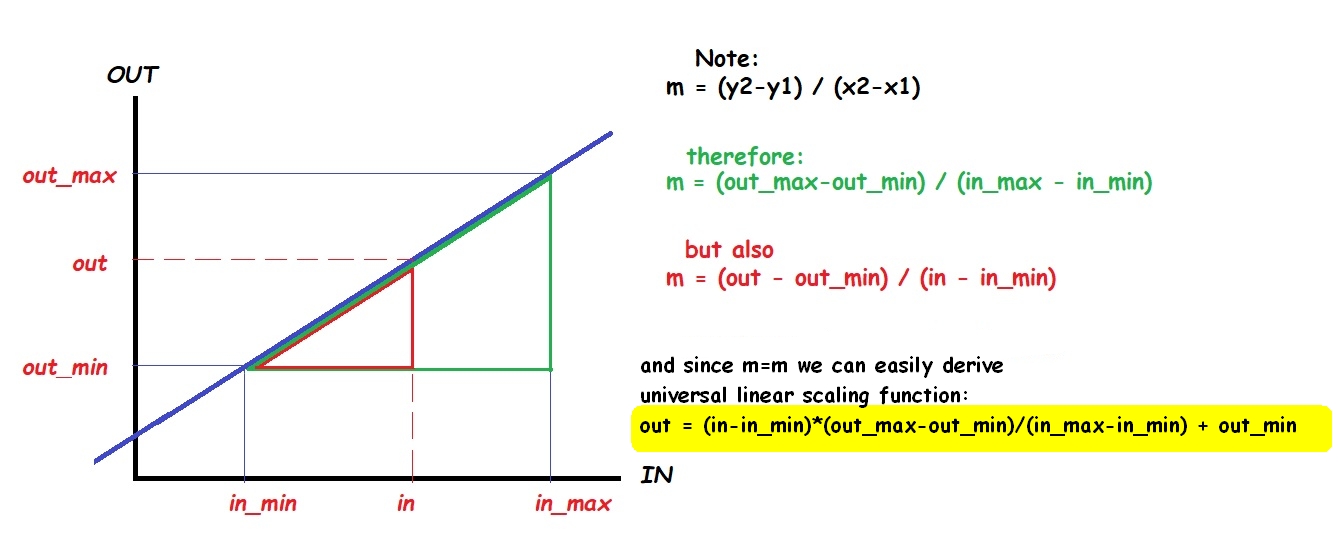
Click PLC has quite nice instruction set, and if scale function is not there, one can just type in the linear scaling formula
https://www.automationdirect.com/clickplcs/free-software/software-instructionlist
https://forums.mrplc.com/index.php?/topic/41761-absolute-encoder-scaling/#comment-190201
-
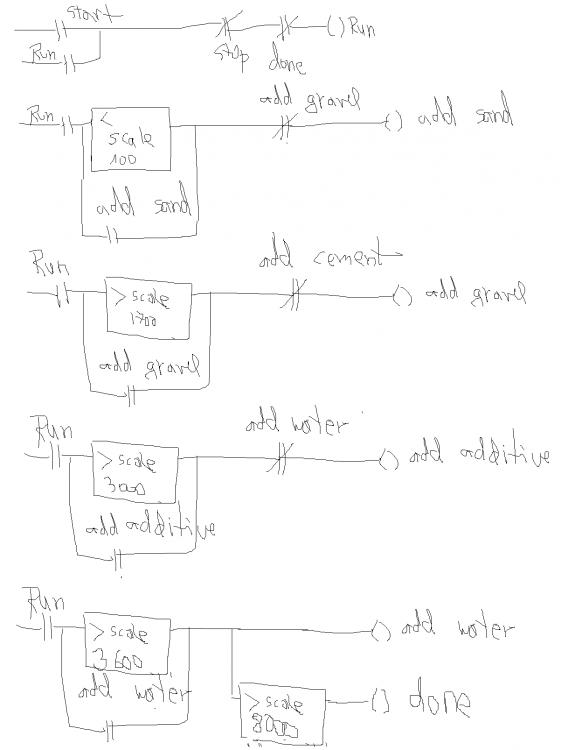
yup. normally it could be output to show if the process is running but it could also be an internal flag or unused output.
this prevents you from holding the start button all day long and it can turn off automatically once the process is complete.
you can think of it as a delegate of the input "start"
-
you may want to add ingredients in certain order to minimize errors. using analog input in your case is simple comparison. instead of hardcoded values use variable and make sure they are retentive (keep value after PLC is rebooted). code should be very simple, something like:
-
Not sure about commonly used. companies i used to work for tend to spec business machines like Lenovo.
i do not like that. pushing hardware spec from top down may be nice from IT perspective but it is not efficient or productive. slow pokes get machines that they are not using and speed demons are stuck on something mediocre. machine need to be selected to match user and applications that user works with.
today, 8Gb ram is very little from my perspective. maybe for ... email ;)
i have clunky old i7 with 32gb RAM with 0.5Tb + 1Tb storage. it is ok if i do not run too many things.
2 people like this -
QuoteAnd don't make me repeat the Sheave / Pulley /Belt versus Chain discussion we had.
why not? it could be entertaining... ;)
-
QuoteI want to just type bSys and let the program autocomplete the whole name (bSystem_Started) by just pressing enter.
well, you may want it a whole lot more and that will still not make it appear for you just like that. when such option is present in the software, it is normally enabled by default. in other words no specific action is needed to activate it but there may be setting to deactivate it if desired (for example if it does not work as expected). in other words you should not need to do any digging for such settings. and based on what you reported so far, it looks like you will have to live without it.
As you can see there is not many responses. in other words nobody is confirming that they have it in that software version. so if you were really serious about finding out about this, you would check manual for your product to see if this option actually exists in your version of software. or you could contact manufacturer. when you pay for software, you are entitled to at least basic support. or you could post some details for those who may be willing and able to help. an example of details is the exact software version, environment in which is installed (OS version, service packs, regional settings and anything that may be unique to your installation). since nobody else reported it as available, it is pretty safe to assume that this is a no-go...
-
well it has to be connected to something. what is the device or program that reads the encode value over the ethernet? you need to add scaling function there.
two readings at two different and precisely measured lengths.
example:
length L1, reading R1
length L2, reading R2.
then apply linear scaling.

-
18 hours ago, Gobot78 said:Thanks so Q series means this exact plc model will be on plc drop down list or how can i remember what selection goes with what plc?
Q series is a family or series of products. Products of one family tend to have similar characteristics such as form factor, instruction set, supported types of expansion modules, memory type etc. individual members of the family will have some differences such as memory size or maybe CPU speed etc.
to get familiar with something you need to spend more time with it. study catalog and manuals, do some programming. really important thing here is to use correct manuals so you need to be able to identify products you use.
1 person likes this


No voltage at outputs even when forced
in Allen Bradley / Rockwell Automation
Posted
yup... probably incorrect wiring. have not use ML in very long time but was helping students with their project and had to try explaining the outputs and wiring a bit more. here is adapted version.
Some ML have mixed outputs. LX32BXBA seem to be one of them. Also all outputs need to be powered - from outside.
Relay outputs are easy to understand, the relay contact is acting just like a switch. And even newbies should not find it hard to understand that every switch needs one side connected to the power and the other connected to the load... And both switch and relay contact will happily handle either AC or DC (within limits, always check specs). And because simple switch (and relay contacts) are not polarized, you can also place the switch (or relay output) in the negative leg of a DC circuit if you want.
To reduce number of termination points, it is very common that inputs and outputs are internally grouped (bussed, ganged) so that single terminal can be used as "common". But this limits options when working with circuits that are galvanically isolated. So to make things more flexible, not all outputs are grouped all together. They may be split into smaller groups so that one can mix and match different loads (AC or DC, positive or negative). In case of L32BXBA, there are four individual outputs (OUT0, OUT1, OUT 8 and OUT 9). Another two relay outputs are OUT10 and OUT11. They are grouped together (they use same supply via terminal DC5/VAC).
Transistors outputs are a bit different. Slightly...
They are polarized so one cannot do all of things that we just described with relay outputs. Also (in general) transistor outputs are rated for less current when compared to relay outputs. But they can be FAST, their signal is CLEAN (no bounce, suitable for pulse trains for example), they can last virtually forever (no arcing and degradation due contact oxidation) and they are much smaller (easier to get a lot of them in tiny package).
in Case of L32BXBA all six transistor outputs are grouped together (they use same supply VDC2 is positive and COM2 is negative). Reason for two terminals for power is that (unlike relay outputs), transistor are 3 terminal devices so input and output are not galvanically isolated. Therefore outputs have driver logic that is powered from same circuit that the outputs are controlling. This means they need negative terminal as well. And since positive is already present anyway (in this case VDC2), there is a terminal to bring the negative supply too (COM2). Without connecting both, those six outputs are NOT going to work.
Finally, I am really not fan of the silly and completely abstract illustrations that this manual uses. So I tried to indicate internal circuitry (relay contacts and transistor outputs). This should help with understanding polarity and easily differentiate the output types. If you are using all outputs to drive DC loads, you may wire them like this: