

kaiser_will
MrPLC Member-
Content count
918 -
Joined
-
Last visited
Posts posted by kaiser_will
-
-
CompactLogix L32E processors have a built-in port for Ethernet/IP.
http://literature.rockwellautomation.com/idc/groups/literature/documents/um/1769-um011_-en-p.pdf
This processor also supports being on a TCP/IP network, but communicates with devices via Ethernet/IP protocol.
http://literature.rockwellautomation.com/idc/groups/literature/documents/um/enet-um001_-en-p.pdf
-
Mover the ACC register into a DINT or a Float, that should keep the HSC register from faulting the processor on math overflow.
-
Which PLC processor do you have?
COP, as you are having trouble with, Source and Destination must be same type (INT).
You want to copy/move part of a source into a destination word...Masked Move (MVM) may be your best bet, allowing you to move part of source to destination.
http://literature.rockwellautomation.com/idc/groups/literature/documents/rm/1756-rm003_-en-p.pdf
The other issue you are going to have is you want to move "32" into bit 7. Data move instructions are byte-for-byte; "32" => 0010 0000 (bit 6 is high). But you want to move "32" into bit 7 => 0100 0000, which is actually "64".
-
What PLCs are at each station? What communication protocol/networking are you using? How much "data" do you want to transfer from station to station with the product? What is the cycle rate of the part?
For this process, consider developing a flowchart of the process. Start small and add as much detail. As you are developing your flowchart, ask yourself how can this step go wrong (i.e., determine all modes). When you determine all modes of operation, this is helpful for determining what alarms to be displayed. A good flowchart would like the process and have handshaking (and mode alarms).
Without a well thought out sequential process, throwing data over the wall (i.e., daisy chain) often has events in which the system fails.
If you have Visio, I can provide flowchart examples.
-
Akif I have been in your position, inheriting a DeviceNet mess "that worked". Working around production, myself and our technicians isolated a DNet connection point, monitored the network to find out where the break was, and took good notes. It is easy to separate the network and ring out wires. However it usually means "breaking" the network, which might affect production.
Dig into the DNet module to find diagnostic history. Work your way backwards.
-
Micrologix 1400: D-Sub communication port supports protocols DH-485, DF1-Full, DF1-Half, DF1 Radio, Modbus RTU, ASCII, DNP3 Slave.
http://literature.rockwellautomation.com/idc/groups/literature/documents/um/1766-um001_-en-p.pdf
Panasonic GT707 HMI: D-Sub communication port supports protocols MEWTOCOL & MEWTOCOL7, General purpose serial (for Panasonic dedicated protocol), Modbus RTU, Other.
https://www.panasonic-electric-works.com/cps/rde/xbcr/pew_eu_en/mn_gt707_hardware_jp_en.pdf
It appears there is no defined DF1 protocol for the Panasonic HMI to communicate with any Logix PLC. You do have the ability to configure communication for Modbus RTU.
-
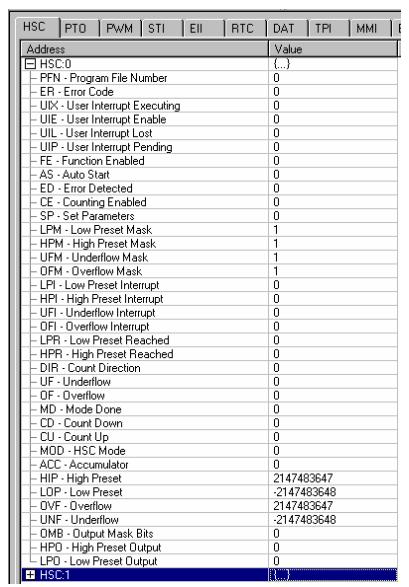
Can you post a screenshot of the HSC tab, so we can see the status of the configuration and the channel?
-
How long does Alarm View freeze for?
What has changed - have you added any new tags?
-
http://literature.rockwellautomation.com/idc/groups/literature/documents/rm/1763-rm001_-en-p.pdf
Read page 107. Logix500 online help will only have so much information. High-speed inputs are masked to HSCx registers. You will get more precision by using the quadrature encoder instead of using a single channel.
http://www.infoplc.net/files/descargas/rockwell/infoPLC_net_hsc_quick_start.pdf
-
How are you reading the high-speed input in your logic? Are you using an IIM?
Is the encoder single-ended or quadrature?
http://literature.rockwellautomation.com/idc/groups/literature/documents/rm/1763-rm001_-en-p.pdf
Dig out the cut sheets for the encoder. Wiring, ML1100 terminals, ML1100 configuration. The PLC channel will need to be configured.
-
Something has changed to your DeviceNet network and the interface card is letting you know it. Poor connection, damaged DeviceNet media, one too many nodes attached. DeviceNet is very rugged and robust, but I have seen many DNet networks show signs of failure and nobody has a definitive schematic of the network. Do you have a good schematic? Start going through the network looking for physical signs of failure, pinched trunk or drop lines, poor connections. We had a similar failure; root-cause - someone pushed the SCADA computer too close to the office wall, shoving the termination resistor to the side and making a poor contact. Had it not been for the cleaning lady, the problem would have never occurred.
-
1794-OF4I => Isolated 4-channel analog output module. In Logix5000, when you add a PLC module, Logix automatically creates read and write configuration words , tags, for you. If you pull up the Controller Tags list, and drill to the rack and analog output module, there will be input and output words. Read the literature; these cards can be used in a multitude of ways, so look for your desired example. You will need to set/reset certain bits to get the desired configuration.
http://literature.rockwellautomation.com/idc/groups/literature/documents/in/1794-in037_-en-p.pdf
http://literature.rockwellautomation.com/idc/groups/literature/documents/um/1794-um008_-en-p.pdf
-
1. Research the PID itself and understand the differences in undershoot, overshoot, unstable conditions, etc.
2. Break the problem description down into blocks. Bit-size morsels is how we code.
3. Learn and understand the PID (or PIDE) function block; it is only 1 block. A code example for 1 rung and 1 block...probably not going to happen.
http://literature.rockwellautomation.com/idc/groups/literature/documents/rm/1756-rm003_-en-p.pdf
http://literature.rockwellautomation.com/idc/groups/literature/documents/rm/1756-rm006_-en-p.pdf
http://literature.rockwellautomation.com/idc/groups/literature/documents/wp/logix-wp008_-en-p.pdf
http://literature.rockwellautomation.com/idc/groups/literature/documents/rm/1756-rm094_-en-p.pdf
-
Class assignment?
1 person likes this -
The SLC 5-/04 has (2) DH+ ports (3-pin Phoenix and round DIN) and a 9-pin D-sub port (that can be used for DH-485, DF1 or ASCII).
http://www.weintek.com/Download/PLC_Connect_Guide/eng/PLC_connection_guide.pdf
Pages 894-895; it appears the limit is capped at 254 but you wish to use 422. Try reducing your bit address, or create a new SLC memory register to use.
1 person likes this -
As b_carlton noted, this pop-up directs you to a log file created when you start the install, and to hold the steps the process stopped with. Open this file in text editor and walk the process back through. AlexMota also notes to take a look at the OS you are using.
-
You are trying to restore a FTView 8 backup application with FTView 7 and it does not work. This is very common.
If this application came from a supplier and you do not have FTView 8, you could try asking the supplier to save as a FTView 7 application.
An alternative is to contact your local Allen-Bradley/Rockwell distributor and ask if they can open and back-convert the application to FTView 7. Being as they are not getting anything for this work, the answer may be "no".
As noted above, there may be loss of functionality in your application if it utilized features not in the newer software.
-
Keep in mind (along with JackDempsey's comments)...with indirect addressing, make sure to add limit tests. If you increment the indexer beyond the dimension of the array, the processor will fault. Unplanned downtime, scrap product created, late order delivery, your name next to a staff note...been there.
1 person likes this -
What A-B PLC are you working with? There is a difference in programming tools.
This example you describe sounds like "indirect addressing".
Expand on what you desire to achieve.
1 person likes this -
Joe E raises a good point...legacy equipment with the PIC box likes Win XP but hates other operating systems. A nifty work-around is a WinXP VirtualMachine loaded on your Win7+ PC; I prefer VMWare Workstation.
Alot of the older PViews do have (2) ports, but read the fine print...one is often DH-485 and the other is RS-232 for a local printer.
When you are tasked with getting something up, always research the details. Assuming a DB-9 port is RS-232 and up for grabs can wind up causing a lot of grief. A brief sort-of primer on SLC processors is attached; something I created to educate the field techs for this very subject.
Read the literature, network the devices, add functionality for you to test communication. HMI status lights tied to PLC addresses; HMI buttons tied to PLC addresses.
Work_Instruction_-_Allen-Bradley_SLC_Communications_Setup[1].doc
-
MOST AC induction motors are capable of 100Hz continuous-duty operation. Before you jack up the maximum VFD speed output, gather data on the motor and how much it is loaded already. If the application is already fully loaded, increasing the speed headroom will do nothing for you.
There are a number of questions to answer prior to making the change. How is the VFD commanded? It could be a speed pot, an analog output from the HMI via the PLC, an Ethernet/IP register from the PLC. Pull out the electrical schematics, go through the PLC program, pull out the VFD user manual.
http://literature.rockwellautomation.com/idc/groups/literature/documents/td/520-td001_-en-e.pdf
http://literature.rockwellautomation.com/idc/groups/literature/documents/um/520-um001_-en-e.pdf
PFlex 520 AC VFDs have parameter P044-Max Freq (typical is 60Hz). Once you have proven that you will not burn up the motor, and once you have insured yourself that the motor is not fully loaded already, with the machine stopped, change parameter P044 and whatever else is needed (for expanding the maximum signal coming into the drive).
-
Although I haven't worked with the PF527 line, I do believe they offer basic V/Hz control. I do not have a code example I can share, but this Work Instruction will walk you through using CCW to add the drive to your project, then use RSLinx and Studio5000 to bring the networked drive into your project. After that, create the safety routine to utilize the STO feature, add motion code and you are set.
Work Instruction - Allen-Bradley PowerFlex 525 VFD Startup.doc
-
Have you read through the Mitsubishi drive manual? You have programmed the drive for the analog input command (i.e., analog current or analog voltage)?
http://dl.mitsubishielectric.com/dl/fa/document/manual/inv/ib0600366eng/ib0600366engg.pdf
You will want to add HMI indicator lights mapped to motor drive status registers (i.e., ON, Faulted, Running, Stopped, Speed Command, etc.). These "idiot lights" come in really helpful with debugging communication.
-
No Rockwell Support Contract (that you know of), No Solenoid Output Snubbers, No washdown-rated electrical panel for the PLC. You have your work cut out for you.
To justify to your management a support contract...ask "what is 1 day of production worth?". The annual support contract value should be a fraction of daily production worth.
PowerFlex 4m
in Allen Bradley / Rockwell Automation
Posted
Page 3-24...Requires digital input required for Run or Start; requires a valid Start contact
http://literature.rockwellautomation.com/idc/groups/literature/documents/um/22f-um001_-en-e.pdf
How is your start/stop circuit wired? 2-wire or 3-wire?
When you power up the drive, expecting it to auto-start, what diagnostics does the drive give you?