

DanW
MrPLC Member-
Content count
381 -
Joined
-
Last visited
Posts posted by DanW
-
-
In 2012, Kepware published a manual for their OPC version at the time. It was definitely OPC DA, not OPC UA. manual is attached.
-
I use the writer app in LibreOffice, a freeware competitor to Microsoft's app Word in MSOffice.
LibreOffice Writer is far less fussy than MSWord when placing graphics on the page. I struggle with Word when I was adjacent photos (on a horizontal axis), not just sequential (vertically one after another). Have to be careful to save docs as .docx rather than their proprietary format, but that's not a big deal.
-
Maybe, it's a big world out there, but I doubt it.
Typical serial I/O modules use either a defined proprietary protocol or use Modbus.
The Advantech Adam 4050 has 8 DO's but only part of the message written is the bit pattern for which bit is on or off. The protocol uses ASCII characrters, with this syntacx (for that specific module) [delimiter character][address][command][data][checksum] [carriage return].
That series of I/O modules does not have RS-232, they use RS-485, so you'd have to use an RS-232/485 converter, or use the Red Lion RS-485 port.
1 person likes this -
One key word under product description is 'single ended'. That means the (-) side of all the signals are connected all together at one point.
The terminal labeled RTN on the Field Wiring Terminals table means return, or the common, (-) side of the input(s).
The wiring diagram shows the field device on the left with its positive output connecteed to In, (-) connected to RTN.
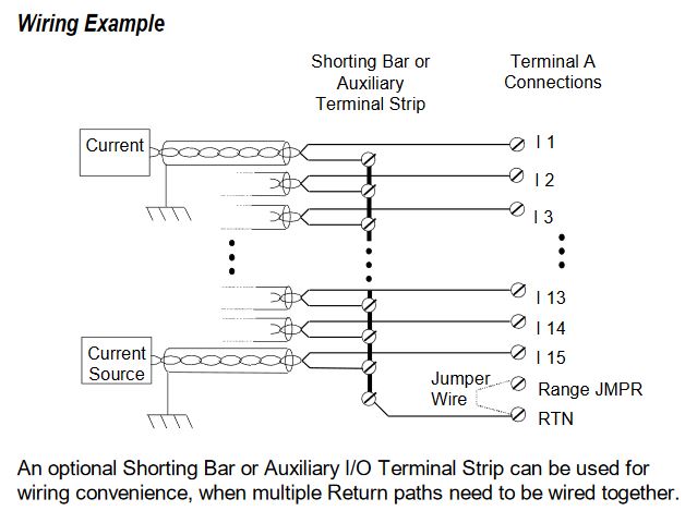
The In (I2, I4) number represents the current source field device (I is current in Ohms Law).
What is not spelled out is what happens when the field device is a loop power transmitter and needs a loop power supply.
So the (+) side of the current signal goes to the An terminal, which is either
- the negative terminal on a loop powered transmitter (because the positive terminal of the transmitter is connected to the Power supply (+), or
- the positive output from a 3 wire or 4 wire field device.and then either
- the negative (return) of the loop power supply output connects to the RTN terminal
- the negative outputs from either 3-wire or 4-wire field devices are run to terminal blocks, jumpered together and then connected to RTN.The wiring diagram essentially shows the same thing -
Test it with a single field device.
I haven't a clue what all the Bn connectors do. Shame they can't be used as RTN or (-) connections.
-
-
The flow meter is clearly a lab unit - it's construction, power source, line fittings, accompanying software and lack of industrial signal interface all peg it as a lab unit.
Writing a conversion protcol driver for the device to get data into a PLC could take hundreds of hours, far more if you're inexperienced.
The flow meter is a thermal dispersion inferred mass flowmeter, similar in size flowmeters from vendors like Brooks, Aalborg, TSI Alnor, MKS. It does have a 2KHz sampling rate, which you might need, but I doubt it. You might consider buying a flowmeter that can interface to the process AND to the data collection or control needed.
@aawilliams Welcome to the forum. Your reply is cogent, readable and a very instructive reply for a first time (?) poster. Nice job. You must be a sojourner from some other controls forum to compose that high level a reply.
1 person likes this -
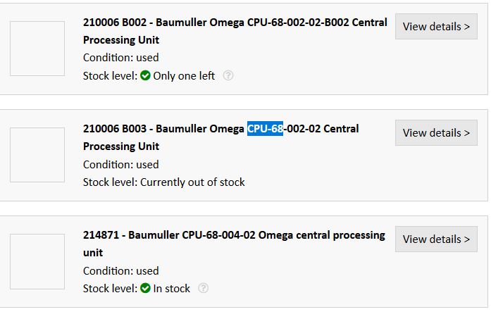
As the software splash screen shows you, it's a BauMuller (u umlaut with correct spelling) product (Omaga makes nothing, private labels everything).
web searches turn up parts described as Baumuller-Omega:
Baumuller is still around. Have one of your buddies who's fluent in German give them a call, maybe an old guy still has an English manual for the old stuff
https://www.baumueller.com/en/products/automation/control-platforms
 1 person likes this
 -
A photo might help identify what you have.
Are you sure 'Omega' is the PLC or could Omega be just the HMI display?
-
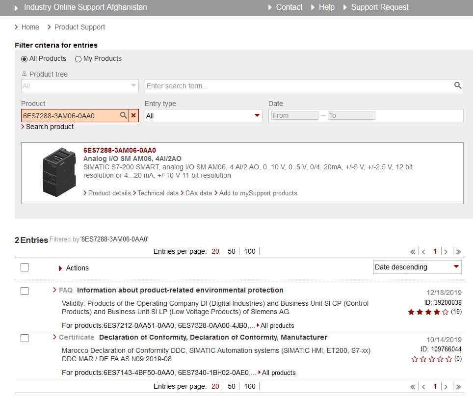
There does not seem to be a manual on the Siemens site. What kind of manual came with it? Have the Germans given up on documentation?

-
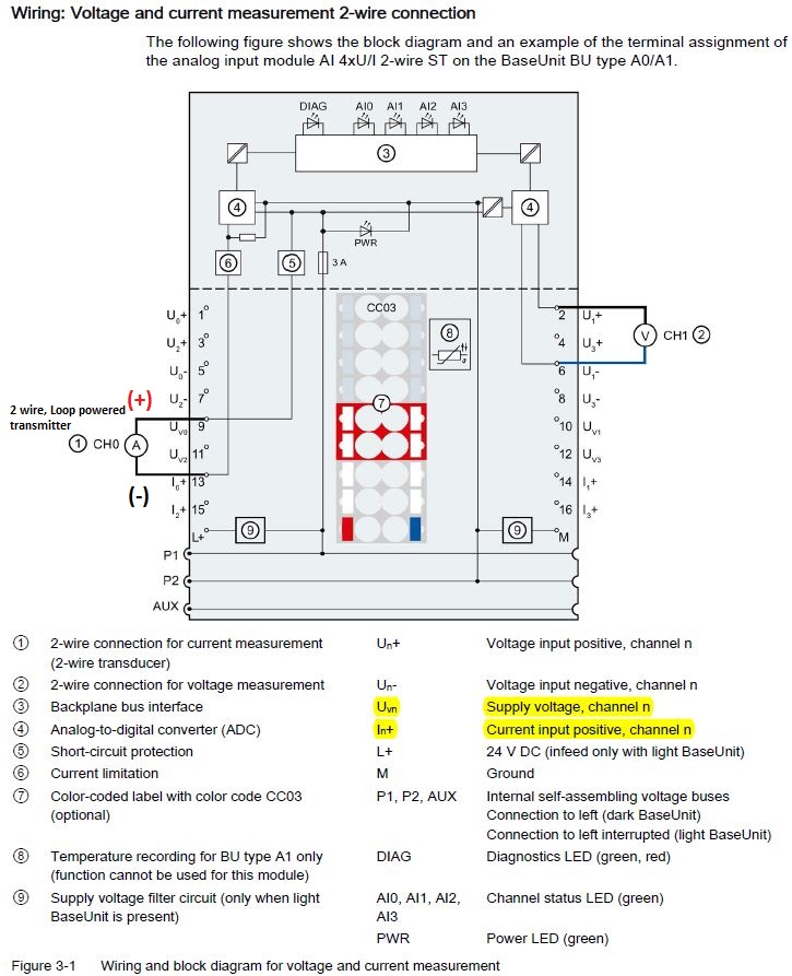
The field instrument is supposed to be a 2 wire, loop powered, passive transmitter, powered by an external power supply source.
That supply power source in the input module is connected to the Uvn terminal. (Uv = voltage supply, n = the input channel number)
DC power, by convention, connects to the transmitter's (+) terminal.
The transmitter's (-) terminal connects to the analog input (+), which for this module is (In) (current = I, n = the input channel number)
Most field instruments are 'floating' and their outputs are not grounded, so there is not likely to be excessive common mode voltage in the loop which would require an isolator. So, no isolator.

-
The typical story one hears when the problem is excessive common mode sounds something like this,
"I had x number of analog inputs connected and they were all fine. Then I added one more and all of them went crazy. What happened?"
An AI card can work within its common mode limitations but adding just one AI can drive the common mode past its limits.
If you can establish that X number of AI's worked OK for some period of time and then when an additional AI was added this overrange situation started, then the last one added is the one to that needs the isolator. An isolator will decouple the common mode and allow the other inputs to function OK.
1 person likes this -
The symptoms are excessive common mode. Some source of common mode exceeding the ±10V limitation is forcing the input above the rail voltage saturating the input, just as Panic Mode describes.
The A-B manual says:


Chances are the AO's on the flowmeters are active outputs and you can't connect the commons of the power supplies because you don't have access to them.
I'd put a 4-20mA isolator/repeater on the one that seems to fail first and hopefully that'll solve it without isolating the other inputs.
-
It does not appear to be a fault in the AI because you can measure the 20mA+ (28mA is some cases), so the AI is jsut reflecting the loop current it 'sees'.
The flow meter's AO should regulate the current in the loop. That's what 4-20mA outputs do. But the flow meter can not prevent currents from ground loops adding to or subtracting from the loop current. It would be unusual if ground loops developed over time. Which makes me wonder, how many of the 16 flow meters exhibit this over-current phenomenon?
Is it the same flow meter's output going high or does this occur over different flow meters?
Are the loops 2 wire loop powered (external power supplied) or active, powered by the flowmeter?
-
Modbus master/clients all have a time-out setting that in the absence of a reply from a slave will skip over it (instead of waiting forever for the reply) and go onto the next task/action. Assuming that the time-out can be flagged, It would take some programming to recognize some number of reply-failures and then drop the missing slave from the line-up.
Yes, slave loss slows down 'throughput' because the master waits the entire time-out interval before moving onto the next action. The 'next' action might be a re-try or it might be 'ignore and proceed'.
Slaves can be wired on an RS-485 multidrop network without affecting the network if the slave is not enabled. But disabling the slave's comm will not speed up the Master's actions. The bad slave has to be taken out of the Master's 'line-up' to avoid the time the master waits for a reply that might not be forthcoming.
-
Thanks for the update.
-
Is it the best way? I don't know. Does it matter how fast the conversion is?
I do know that there four different word/byte (IEE754) formats for 32 bit floating point values, two of which are commonly used in Modbus.
Many Modbus master/clients provide the ability to pick one of the two to use to interpret the raw data.
If your master/client has a choice for floating point formats, you could try the alternative one and see if it does the conversion properly with the raw data, before moving the data.
-
If it sorts inversely, then move the data words to change their order of the 16 bit data words and convert to float
D0: BE62 move to D2
D1: 31D7 stays in D1
D1: 31D7
D2: BE62new inverse of the sequential data D1 D2 is BE6231D7; convert D1 D2 to the correct float
-
The format shown in the 5th screen shot (2.4) is a Modbus RTU query and response, so I would expect that reading the three values can be accomplished with a Modbus instruction. The advantage of using a commercial Modbus firmware/routine is that the nitty gritty of stuff like calculating the CRC already done for you. In fact the following screen shot mentions Modbus. The data field in the answer is not correct. It says 3 bytes, but shows 6 bytes (3 registers). The Modbus Function Code 06 is normally a "write single 16 bit register", so you'd have to write each register value one at a time with separate 'transactions'.
I suspect it'll work, however, I have zero experience with either master or slave.
-
I would try turning off CTS control (Port 2 settings)
I have no idea what 1:N protocol is, do you?Given how close it is to Modbus, can you try Modbus RTU protocol?
-
You shouldn't split threads, because people won't see both.
I don't know what cx protocol is, but some RS-485 devices need physical jumpering for half duplex operation - where the Tx negative is jumpered to Rx negative, Tx positive is jumpered to Rx positive.
-
It uses the Modbus RTU 'read Holding register' message format, so the stuff that creates a 'can't connect' Modbus RTU situation applies.
Here's my list, if it doesn't apply, like the multidrop items, skip it.
Modbus RTU over RS-485 'can't connect' issues:
- do both ends have Modbus installed and enabled ? (Modbus frequently an option) RS-485 is NOT Modbus, it is a hardware bus.
- Right protocol? RTU or ASCII protocol being used? - neither is compatible with the other
- is slave field device powered, connected and on-line?
- Correct pin-out for RS-485 on an RJ-45 or DB-9 connector, or any non-screw terminal connector?
- DB9 gender changer adapter is a null modem adapter
- DB9 shell is grounded, common mode pulls down the network
- RJ11/12/DB9 adapter wiring is faulty, wrong, missing
- RS-485 cabling connected and integral for entire run?
- use of non-shielded, non-twisted pair cable
- serial settings identical on both ends? RTU uses 8 bit data word, 1 start bit, 1 stop bit, parity? 2 stop bits can be a no-go; ASCII 7 bit data word
- has the power been cycled after serial comm settings were configured to force the recognition of the changes?
- RS-485 A/B driver lines backwards. Even though should be (+) to (+), (-) to (-), labeling is not consistent vendor to vendor. Try swapping the A/B driver lines.
- serial port powered 232/485 adapters on laptops frequently fail to operate if not powered by external supply because laptop serial ports limit power to the serial port to conserver laptop battery power
- Using the wrong COM port - USB/485 converter installed on virtual COM port - check Windows' Device Manager > ports
- RS-485 signal ground is case ground - excessive common mode swamps the RS-485 signal. Solution - RS-485 isolator/repeater module
- lack of 3rd wire signal ground causes common mode fault
- older 485 signal driver can not handle the number of multidrop nodes
- more recent vintage USB-485 converters do NOT jumper Tx(-) to Rx(-), Tx(+) to Rx(+), check wiring
- 232-485 converter DIP switch settings for serial or soldered resistor for intercharacter delay
- faulted driver is locking up the network - one device can pull down an entire multidrop network
- two or more masters on an RS-485 network will fail - PDU collisions
- master time-out set to infinity - lack of comm to one faulted slave on a multidrop locks master into infinite wait for something is going to happen
- bus wiring issues - junction box misconnection, JB flooded, shield continuity broken at JB, stranded wire whisker shorts
- cabling run exceeds the capability of RS-485 for distance vs baud rate. The 1200m max spec does not apply to baud rates > 90k.
- stub wiring at multidrop nodes causing reflections which create 'noise', false data bits.
- Added biasing resistors load the drivers
- terminating resistor somewhere other than the 485 bus end nodes
- attempted full duplex operation for a protocol that is by design, a half duplex protocol
- addressing the wrong slave, getting someone else's reply, or no reply if there is no slave at that address
- slave node ID can NOT be 00. Master uses 00 to broadcast a message to which a slave is not to reply
- electrical noise on the data lines causes fake start bits, continuous errors, real data never gets through -
Thanks for pointing out Automation Direct's several different thermistor input cards. Not a lot of vendors offer a thermistor card.
-
Presumably you want temperature units.
There are not a lot of resistance-to-4-20ma transmitters that linearize to a thermistor curve. The one I know of is Acromag's TT230, a single channel thermistor transmitter that has "Customizable thermistor linearization table with preset curves for popular resistances".
A PAC I use has an 8 channel RTD input card that has several straight resistance input ranges, 0-200, 0-500, 0-1000, 0-2000, and 0-4000 ohms with programmable look-up table functionality for conversion to temperature units.
I suspect that most RTD input cards have some configurable resistance input option, but you'd have to investigate.
Considerations when using a multiplexor
Synchronizing an external multiplexor to the input scan of a PLC could be a challenge if the Mux is not driven by an external pulse. A mux's solid state switch (as opposed to dry contact switching) might not be designed for switching resistance and affect the measurement. -
That will certainly work but now you have to activate 2 switches.
13/14 is SPST. If it were SPDT with another terminal for the open position (as shown), say 13/14/15 then with only one activation you could ground the input through the unpowered 10K pot which is effectively a grounded input which should give you zero volts (I'd try it just to make sure that is doesn't draw a bias current somewhere and give you an offset).

ANYBUS GATEWAY AB7844
in General Topics - The Lounge
Posted
I've never used Anybus, but their demo program for the config software appears to be the same model you have. It might be worth 4 minutes of you time to watch it.
https://www.anybus.com/products/gateway-index/anybus-xgateway/configuration-manager