

Remon2000i
MrPLC Member-
Content count
24 -
Joined
-
Last visited
Posts posted by Remon2000i
-
-
Dear /Jlolonergan
Thanks for your support
i tried to searche about 0:1/1 but i didnt find it .
i am sorry for this . can you kindly help me in this i will attatch for you my file for this anntena . can you see it ?
best regards
remon
-
Dear jlolonergan
This is rotatable antenna
when my company received the project I found this rotatable antenna was dead
1-the drive not working and fault 50 pole calc fault I
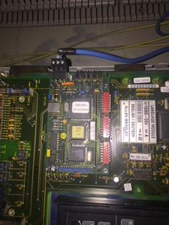
2-no communication between 1747sn scanner and remote I/O 1336GM1
3-panel view 550 give me alarm 24 and it didn’t loading
I treat this problems through
1-changing 3IGBT and changing at value of RPM for motor from 970 to 950
2- I went through Rslinx and Rslogix 500 and I made changed at g files to make communication between 1747-sn and 1336GM1 so the communication happen now .
3-i bring anew panelview 550and installed the software on it .and the rotatable antenna start functions work .
4-The dip switch setting it is correct as industrial company recommended and if it wrong I will not get communication between 1747sn and 1336GM1
5-yes when I give command all system working and the contactor go enable through any order
6-yes I can see the frequency command through my soft ware and HIM module and both give me 0 and stoped 0.00HZ
7-I will attatch two pictures one for dip switch and another for parameters in side drive
8- my number +96550848236 I have honor to communicate with you
best regards
Remon
-
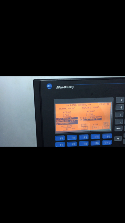
This photo during running the drive and must write for me on panel running in stead of stand still you can see
best regards
Remon
-
Dear joe
I made some investagation and i catch some point 1- drive make out the frequency and give me stoped
2-plc system didn’t see the drive when it working because I have rectangle in side my panel view give me feed back about the frequency of the drive it give me 0 and drive running.
3-I remove the cable between scanner and remote I/O and i give order for plc i found the drive also go out frequency and give me stoped.
4-I made as flow chart at page 41 and I didn’t found any stop owner set to 1
also start owner didn’t give me any bit 1 when I give command .
so I expect the problem in side plc system because I set in the drive
NO :111 DATA IN A1 :28
NO :119 DATA OUT A1 :66
so I want make sure about rs logix 500 it is the same channel but I don’t know way how I can check this option I don’t know the way .
thanks for your support
best regards
-
Yes I did it before but the same result drive stopped.
best regards
-
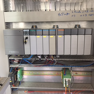
Thanks my dear I will give you more details about my machine.it rotatable antenna .it have to sections low band and high band and this rotatable antenna can change it’s angle through plc system slc503 ,panel view 550 ,scanner card 1747sn ,3input module and one output module .
the scanner connected to drive through 1336GM1.
i can’t give plc system order for frequency above 48 . Not allowed
i will update you when I get anew result .
best regards and a lot of thanks for your assistance.
-
Dear joe
drive didn’t response for any command over communication link it give me stoped and still stoped until me push green button so the frequency go out and I can increase the frequency or decrease it from key bad HIM module
I want drive respond for communication link .
Best regards
Remon
-
Dear Joe
No 28 =48HZ
minimum frequency zero
kindely see this troubleshoot manual page 41
http://literature.rockwellautomation.com/idc/groups/literature/documents/tg/1336s-tg000_-en-p.pdf
best regards
-
Thanks for your reply
yes I wrote parameter no 28 =48 .
and i didn’t have TB3 at all in my drive .
thanks for your support.
best regards
-
Thanks for your reply
yes I wrote parameter no 28 =48 .
and i didn’t have TB3 at all in my drive .
thanks for your support.
best regards


-
When plc give vfd frequency to work on it .
Best regards
-
Hey guys
I need to your support
I have plc system Slc503 connected to 1336 plus via 1747-sn scanner and remote I/O module 1336 GM1.
Communication led at scanner fixed green and four leds at remote I/O module 1336 GM1 green . it mean I already have true communication between plc system and 1336 plus VFD .
when I give order to plc system the VFD didnt carry out the order . when I press on start button on HIM module at vfd the frequancy go out from the VFD and motors working .
THE PROBLEM : VFD DIDNT RESPONSE FOR PLC SYSTEM
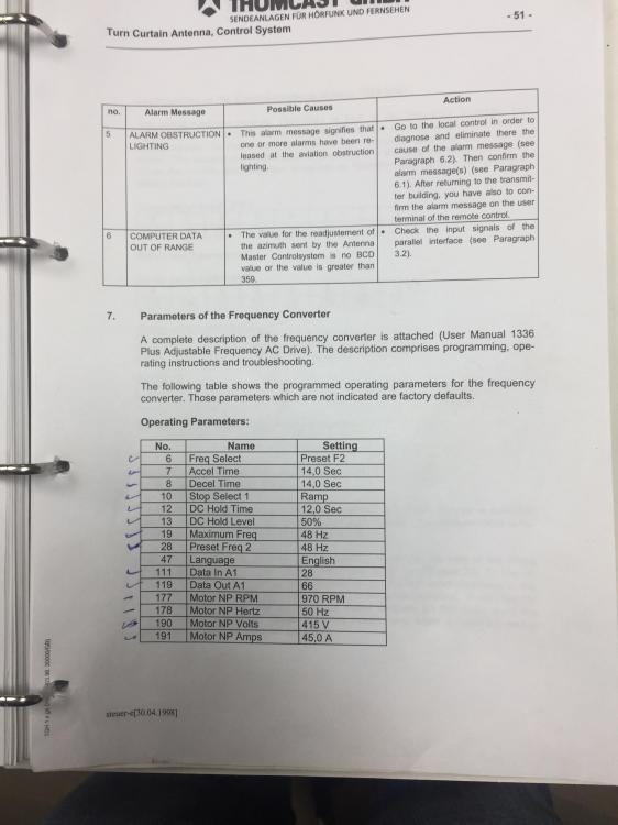
KNOWING THE PROGRAMING POINTS AT VFD
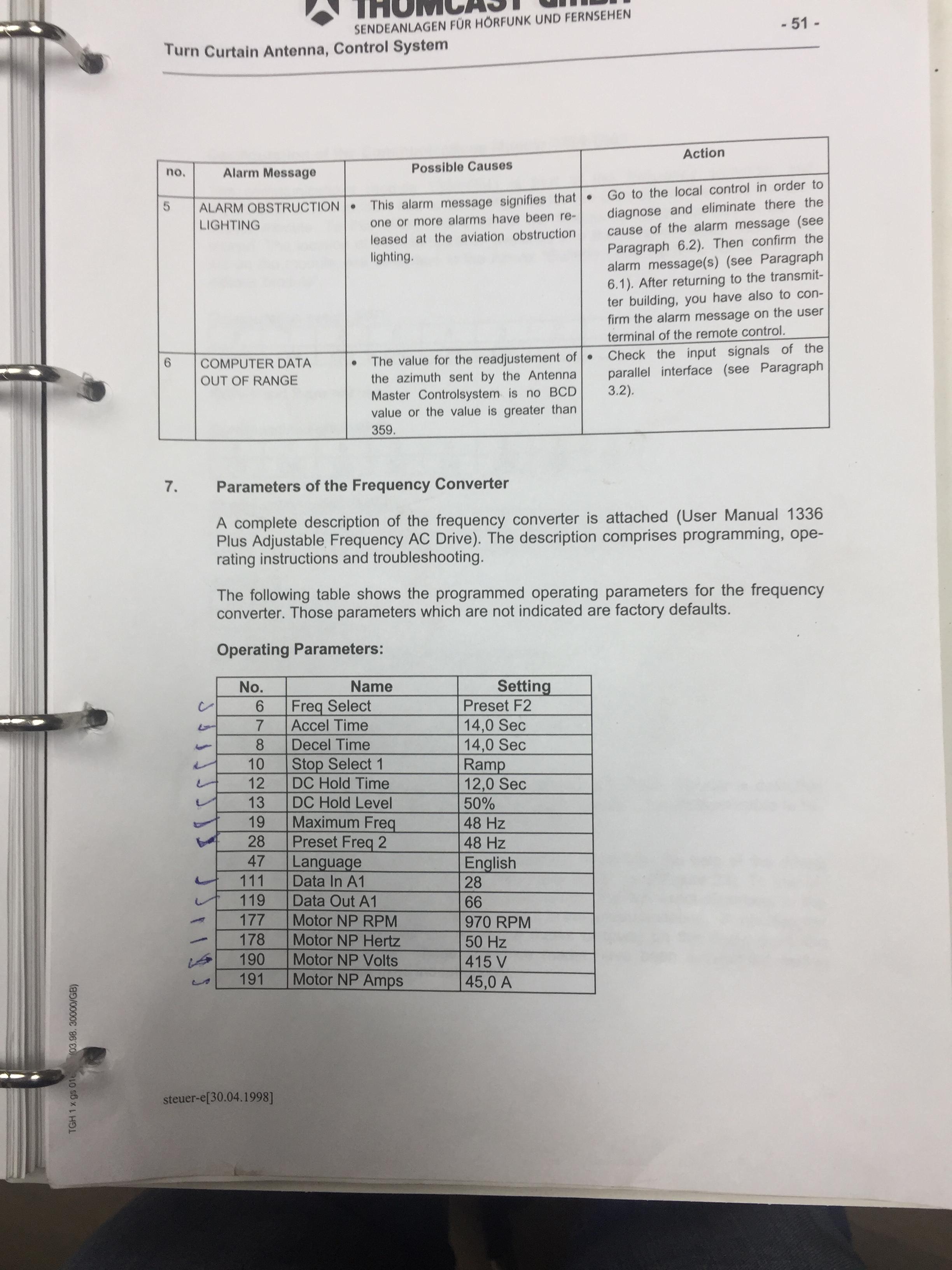
NO 6: FREQUENCY SELECT :PRESET F2
NO 7 :ACCEL TIME :14 SEC
NO 8: DECEL TIME :14 SEC
NO 10:STOP SELECT1 :RAMP
NO 12 :DC HOLD TIME :12 SEC
NO 13: DC HOLD LEVEL :50%
NO 19: MAXIMUM FREQUACY :48 HZ
NO :28 PRESET FREQUANCY 2: 48 HZ
NO :111 DATA IN A1 :28
NO :119 DATA OUT A1 :66
NO : 177 MOTOR NP RPM:950 rpm
NO :178 MOTOR NP HERTZ : 50 HZ
NO :190 MOTOR NP VOLTS :415 V
WHAT CAN I DO TO MAKE VFD 1336 PLUS RESPONSE FOR PLC SYSTEM ?
ALOT OF THANKS TO ALL
BEST REGARDS
-
A lot of thanks m’y dear . I owe to you with this. But I don’t have backup from my application and already at my site I have anew one .
And the panel didn’t open to can load application from it .
best regards .
-
Thanks for your support my dear but I am begginer.how can i make reflashing.
Best regards
-
Thanks for your reply my dear but I can’t see the answer no any way can I take the program from old one and put it on new one
-
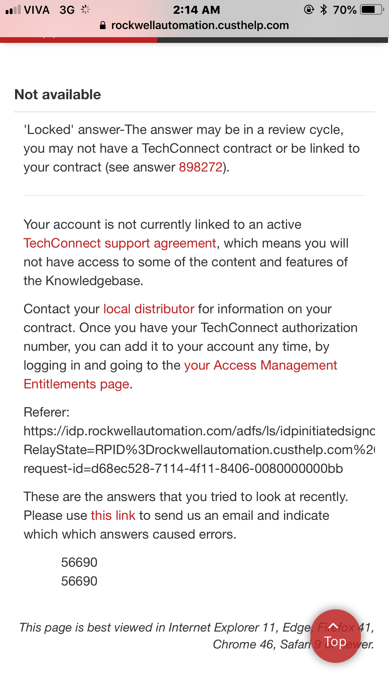
3 hours ago, Remon2000i said:hi guys i have panel view 550 cat : 2711-k5a2 & ser:E
fail to loading give me auto test 24 error
any one facing this problem before .
can any one help what i can do ?
Remon
best regards
(1).jpeg.347c17ca204858e5d618b2e3d287aae6.jpeg)
.jpeg.fc922b8c774d9bd8865d47cd77675592.jpeg)
-
hi guys i have panel view 550 cat : 2711-k5a2 & ser:E
fail to loading give me auto test 24 error
any one facing this problem before .
can any one help what i can do ?
Remon
best regards
(1).jpeg.1e46422f36eb7c01bff90afe066d4401.jpeg)
.jpeg.f1d64b2e155a457015ae7ae77c003221.jpeg)
-
On ٤/٣/٢٠١٨ at 10:22 PM, Ken Roach said:It's very likely that whatever happened to the drive to destroy its IGBT transistors also damaged the 1336-GM1 interface board.
If there are other RIO devices on the daisy-chain network, then you can check the status bits for the 1747-SN scanner module to see if those are working correctly.
Otherwise the probable answer is to replace the 1336-GM1 interface board. While these have not been manufactured for many years, they may be available as replacement parts from Rockwell or on the aftermarket.
dear ken roach i found in our store anew card from 1336gm1 and i replaced it but the same issue .
what is your advice for my status ? how i can check the problem ?
thanks
best regards .
-
Sorry this Vedio not related for our conv
") ersation
ersation
-
Thanks for your reply in the site I have anew card from scanner and I replaced it and also not working .
I searche about 1336GM1 board and i found it on eBay site but I have doubt on it because some board written on public used .
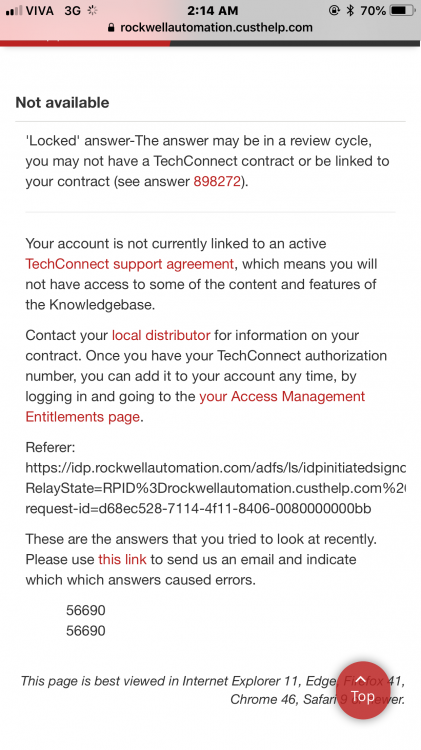
no any way to can assure from problem from this board ?
when I search about this problem I found this sheet .
-
1- yes before I had fault inside vfd serial fault (10) and I found in side vfd 3 IGBT was burn and I changed it now it working ok .
Thanks
-
No one can help me
-
i am new in plc and i have issue with allen-bradley system
processor slc 503 slot 0
scanport slot1 comm led give red flasher no fault an it connected to 1336 plus (vfd).
at scanport dip switch 1&2 on baud rate 57.6
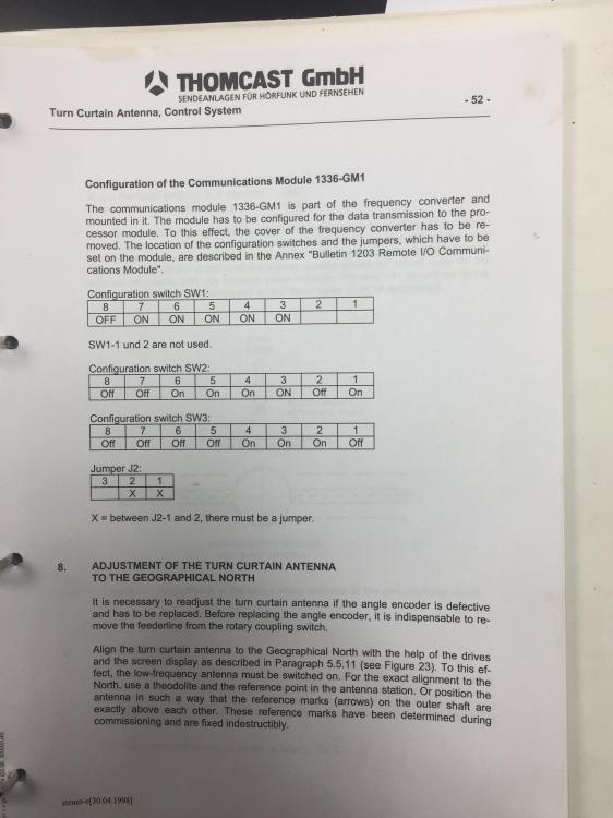
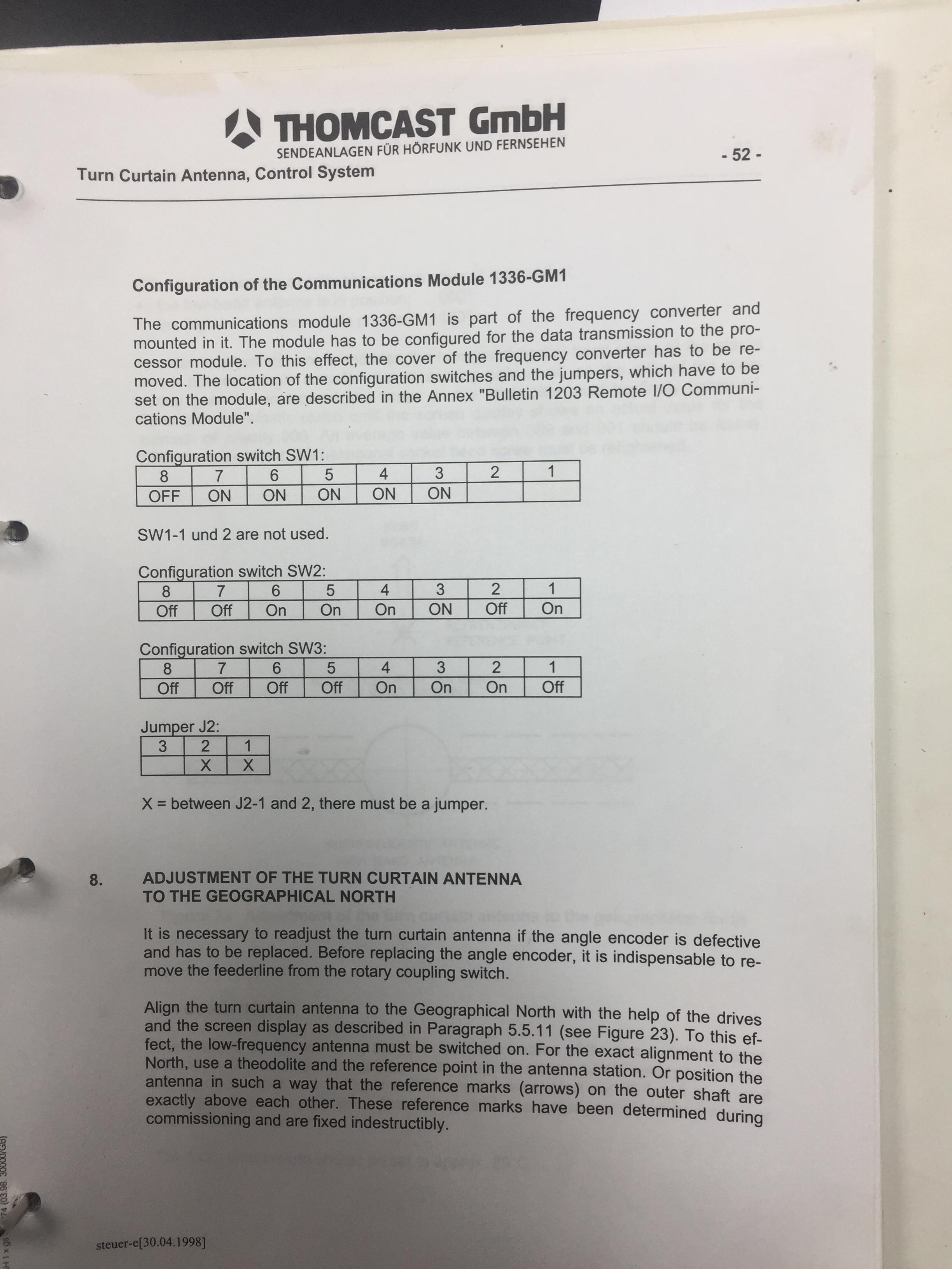
and dip switch at 1336 plus (vfd) i have three switches in remote I/O 1336-GM1 configerd as
SW1: 1 OFF &2: OFF& 3:ON&4:ON&5:ON&6:ON&7:ON&8:OFF
SW2: 1:ON &2:OFF&3:ON&4:ON&5:ON&6:ON&7:OFF&8:OFF
SW3 1:OFF&2:ON&3:ON&4:ON&5:OFF&6:OFF&7:OFF:8:OFF
JUMPER J2 BETWEEN 1AND 2
at scanport terminal resistor 150 ohm
HOW I CAN MAKE SCANPORT COMMUNICATE WITH VFD 1336 PLUS ?


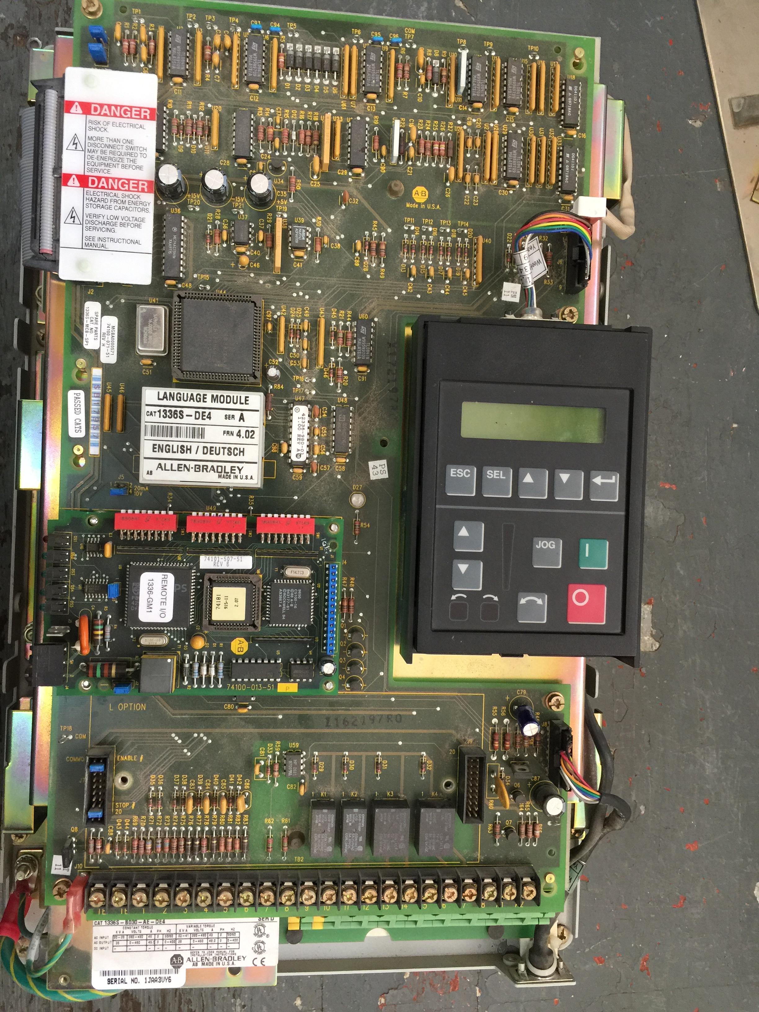
1336 plus (45 A /22 kw)
in Allen Bradley / Rockwell Automation
Posted
Dear jlolonergan
I am sorry for late reply
hooked up with serial port another slc 503 for remote cabinet at the station building.but the local system didn’t response for remote cabinet I will check this problem later .
The manufacturer equipment didn’t have any additional setup .
best regards
Remon