
92 files
-
NJ/NX Get IP Address
By photovoltaic
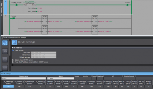
A Library containing a function Block that can be run on any Omron NJ or NX PLC. The Function Block will retrieve the host PLC's IP address, Subnet Mask, Gateway, and MAC Address. The Port Details are displayed through 2 structures , 1 per-port. In the event you only have 1 Ethernet port then the structure for the 2nd port will contain all 0s. Data Format:
IP Address - USINT[4]
Subnet - USINT[4]
Gateway - USINT[4]
MAC - BYTE[6] (hex value)
Access the retrieved details by the typical parent-child tag structure. ex. Port_1_Detals.IP_Address[0] will get the first octet of Port 1's IP.
Tested on: NX1P2, NX102, NX502, NX7, and NJ301
IMPORTANT: This Function Block should not be run immediately after startup. Allow the PLC a few seconds to establish a connection with the Ethernet network.
76 downloads
Updated
-
Function block RANDOMIZE on ST
By drYurban
PRNG algorithm packed into a functional block. As an example of using ST language for Omron CJ series PLC.
43 downloads
Submitted
-
Function block on ST for algorithm DIFU DIFD
By drYurban
An example on ST is the definition of the fronts of a discrete signal.
29 downloads
Submitted
-
valve_control
By drYurban
A working example of an FB to control a valve from an HMI panel. Controls closing/opening times, plus a little visualization.
51 downloads
Submitted
-
CRC16 CCITT FALSE
By k0smas
This checksum was made for the communication of Omron PLCs to the Digitax SF servo drives (Sankyo SFLAG) through RS485. The communication manual for the servo is also available.
24 downloads
Submitted
-
my BCD to BIN CONVERTER
By suresh_
here sinple logic similar to BIN function. Note:no need of error flag here bcs in case of input error, converted output is set to #0000 (on the contrary BIN function activates error flag bcs is keeping last valid value).
9 downloads
Submitted
-
my EXPONENTIAL INTEGRATOR (1st ORDER SYSTEM WITH LAG)
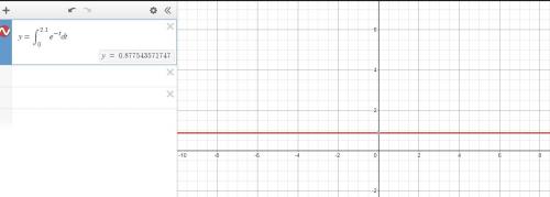
By suresh_
here integrating function from T=0 to T=2.5 with POWER SERIES and error correction. D250 simulates behaviour of first order system with lag.
11 downloads
Submitted
-
my QUADRATIC SIGNAL INTEGRATOR
By suresh_
here simple fucntion that calculates TIME integral of a quadratic signal with Coefficient (Real number). Error correction section is provided. Note: Input TIME and COEFFICIENT.
6 downloads
Submitted
-
my LINEAR SLOPE/TIME INTEGRATING FUNCTION
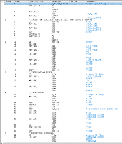
By suresh_
asic integrator provided with error correction section. Inputs are SLOPE * 1000 and TIME *10. No need of PIDAT so it can run on a PC.
INTEGRATOR_02.cxp
6 downloads
Submitted
-
my HELLO WORLD (Lorem Ipsum)
By suresh_
here Hello World ( Lorem Ipsum) in CX programmer via String Data Type. Nice to have when dealing with HMI.
11 downloads
Updated
-
my FEEDFORWARD PIDAT CONTROLLER
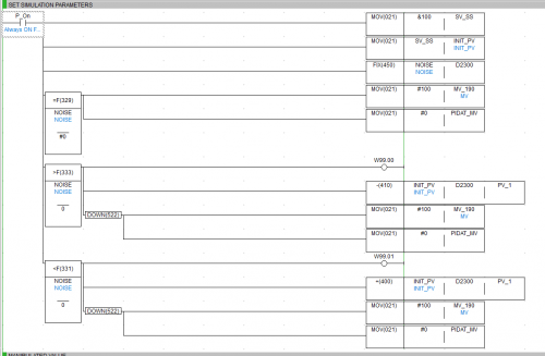
By suresh_
in this sample +/- NOISE signal affecting the Steady State is feeded to PIDAT controller to keep the process stable and reactive. Note: PIDAT function is not implemented in CX simulator.
23 downloads
Submitted
-
my 3X3 MATRIX OPERATOR
By suresh_
simple algoritm for 3x3 matrix multiplication. Tot. Nos. N x N FOR loop will be required to do the math (9 in this case). Refresh every time one input value is changed. Reduction of FOR loops via nesting may be applied.
8 downloads
Submitted
-
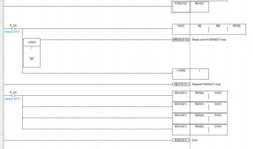
my FOR NEXT LOOP
By suresh_
here a simple example of Array multiplication using a FOR_NEXT loop. It should be stressed that BREAK instruction is fundamental to operate the FOR NEXT loop correctly, on the contrary N: Number of loops ( #DADA in the sample file) of FOR instruction is not so important ( has to be <> #0 anyway ) .
16 downloads
Submitted
-
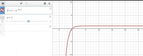
my UNIT STEP RESPONSE
By suresh_
here simpliest 1st order system response to unit step function. Due to Power series limitations, exponential coefficient * time in sec should be < 2.5 to avoid unaccuracy in the results.
5 downloads
Updated
-
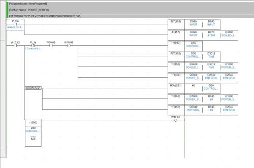
my POWER SERIES INTEGRATOR
By suresh_
In this simple example, approximation via power series is used to simulate the response of a 1st order system [H(s) = 1/(s+a)] Note: input of power series should be less than 2.5 to avoid non linearity in the response.
4 downloads
Submitted
-
my PIDAT CONTROLLER PLUS DEADTIME
By suresh_
here a control loop capable of simulating a PID controller that is regulating a process with variable DeadTime. To run the simulation it needs the following: 1Nos. PLC ( CP1E is fine) with 2Nos. AI and 1Nos. A0. A signal generator hardwired to AI 90 can be used for simulating Disturbance of the Steady State ( SP 125 Units e.g.) . Note: i)AO 190 is hardwired to AI 91 (MV). ii) the process has no dynamics except for DeadTime.
12 downloads
Updated
-
my HYSTERESIS CONTROLLER
By suresh_
here a simple controller useful for operating an AO with Hysteresis. Proposed range is 50 - 200, SP 125, Hysteresis +/-10. Additional Note: an Hysteresis circuit in parallel with a PID controller can be used for tuning complex feedback systems.
13 downloads
Submitted
-
my Time Integrating Function with PIDAT
By suresh_
here a very simple program for time integration of an AI using SCL2 and PIDAT capability. Integrand is sent to PIDAT SP, PV is 0. Note: in the example integral from 0 to 60 sec of 100 AI is scaled to 6000.
10 downloads
Updated
-
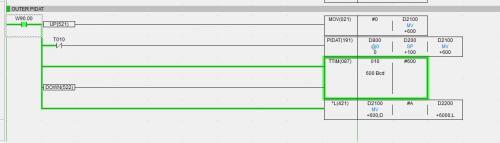
my CASCADE PIDAT CONTROLLER
By suresh_
in this example we have 2Nos. Ai , 1Nos. AO and 2Nos. PIDAT. The PIDAT in the outer loop has Temperature of liquor inside a reactor (SP of 75°C) as PV.The inner PIDAT is controlling the final element of the loop with lower inertia, ie steam Temperature inside the jacket. Finally the steam valve feeding the reactor jacket is controlled by combined action of both the PIDAT. SP of steam is 175°C.
15 downloads
Submitted
-
my TRAFFIC LIGHT LOGIC WITH TRAFFIC DETECTION
By suresh_
here a simple application of traffic light logic capable of incrementing Green Light timing according to traffic flow measured in the same direction (North_South and West-East direction). For each veichle detected in the intersection when traffic light signal is Yellow, 1sec increment of Green Light timing will be booked for the next cycle and viceversa for the opposite direction.This should ease traffic flow during peak time.
20 downloads
Submitted
-
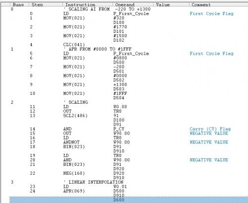
SCL2 + APR
By suresh_
here a an example taken from Omron manual where a temperature range from -200 to +1300 is linearly shifted to a #0000 #1FFF range. It can be useful when a -/+ temperature signal is sent to PIDAT controller.
20 downloads
Submitted
-
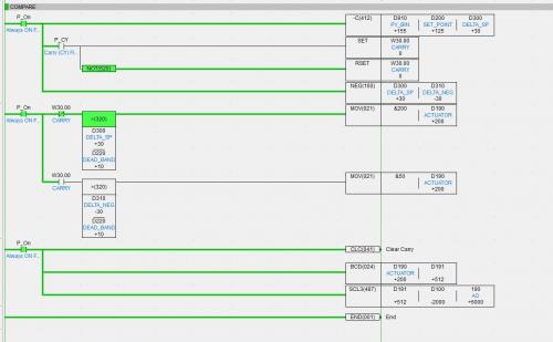
my DEAD BAND CONTROLLER ON/OFF
By suresh_
in this simple example, very similar to the previous one, 190 AO is controlling the actuator at 0% 50% and 100% of is operating range and 91 AI is providing PV for the error comparator. This control could be beneficial where keeping exactely the SV is not mandatory plus the actuator is operating poorly in the proportional band.
9 downloads
Submitted
-
MY AO DEAD BAND CONTROLLER IN CX PROGRAMMER
By suresh_
here my simple dead band controller for Omron CP PLC with Analog IO capability, other than that you may have a precise Voltage/Current reference + multimeter, however the controller can work in simulation mode too because only basic functions have been implemented. Proposed values are: Range 50-200, SP 125, dead band +/- 20.
8 downloads
Updated
-
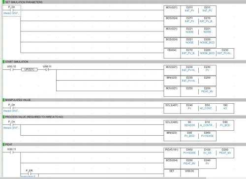
MY PIDAT CONTROLLER SIMULATOR IN CX PROGRAMMER
By suresh_
this is my PIDAT simulator for CX programmer. D100 is the Steady State (50BCD in the example), D410 is (simulated) Process value. It needs a Omron PLC ( kind of CP1E) with n.01 AI, n.01 AO ( AO needs to be wired to AI to run the simulator). When starting set D410 (0:100) and start PIDAT to see the regulator at work. Keep AT OFF to see tracking process.
22 downloads
Updated
-
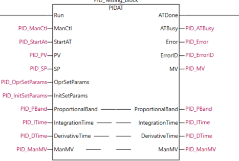
Sysmac Studio Simple PID Example
By photovoltaic
A simple test program and starting values for the PIDAT instruction in Sysmac Studio. Simply run the simulator (Simulation-> Run) and toggle the Test_PID bit. Simulated feedback will allow the loop to operate normally. The setpoint can be adjusted by modifying the PID_SP variable. There is a pre-programmed data trace that traces the SP, MV, and PV.
To use the data trace navigate to DataTrace0 and start the trace, flip the Test_PID bit true and the trace will log 10k samples. Change the SP and view the behavior when the trace finishes.
62 downloads
Updated