

T J SHARON
MrPLC Member-
Content count
52 -
Joined
-
Last visited
Posts posted by T J SHARON
-
-
Hi Dan,
Thanks for the reply.
I will try as u said.
-
Hi Dan,
Thanks for the reply.
Yes, Values in open circuit fluctuates as the previous video. 0v is acceptable
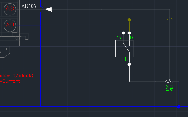
SPDT as show in the pic?

-
hi Dan,
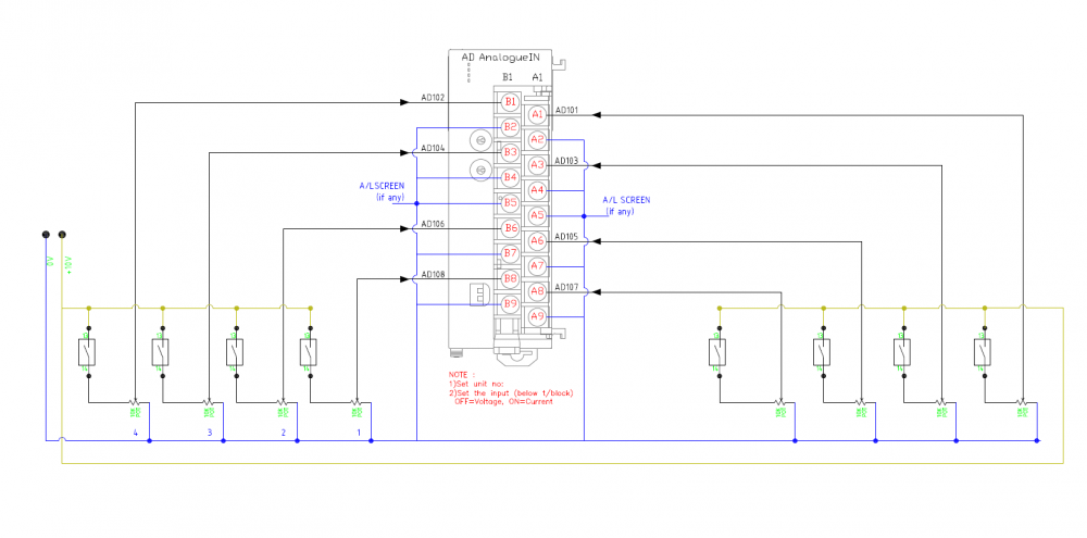
1) those are button switches in the control console.The reason added a switch to prevent someone accidently using potentiometer.
2) these are voltage signals.
3) Pure voltage from PSU to the ADunit via push button and potentiometer
4) Currently i don't have have any screens. Just copied from the manual for future use. but fluctuation reduced after i connected A5 & B5 to 0V.
5) the values should be &0-4000 UINT. high count is only on open circuit condition. The values are accurate and stable at closed circuit.
-
okay . thanks alot
-
HI,
I am re-posting this thread as i did'nt manage to solve. The AD conversion values are fluctuating during open circuit (refer to video).
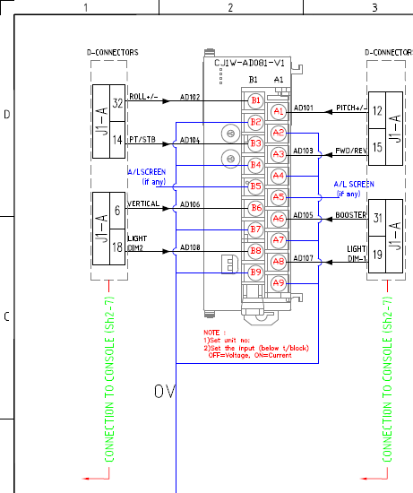
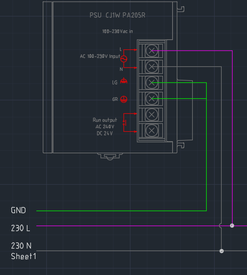
And values remains stable once it is powered.My 8 AD channels are sharing power supply. Refer to pic.
Appreciate all help and suggestions.
thanks
-
HI,
I still didnt manage to get it done.
The values are fluctuating ( like 6555**, FFF** etc) during open circuit and potentiometer is low resistance.
And values remains 0 during open circuit and potentiometer at high resistance(no fluctuation).
My 8 AD channels are sharing power suppply.
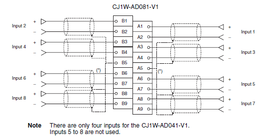
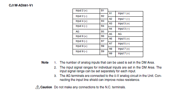
DO i need connect anything to AG terminals.
Appreciate all help and suggestions.
thanks

-
Hi,
Thanks a lot for the suggestions.
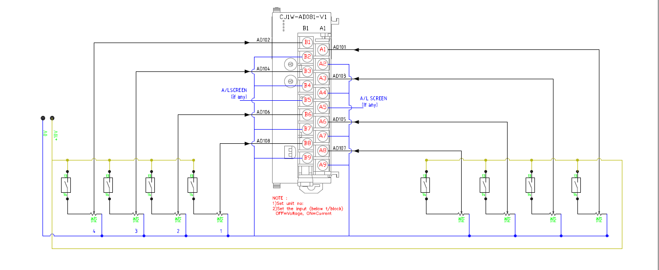
1)For the ADs i used IO table to setup changed CH1-8 to enable and 0-10V in (All voltage/current hardware dip switch set to off). I am not sure whether any open circuit static V or anything like that. ( wiring attached, Blue color cable to 0V. A5 & B5 are NC).
2) For the data writing issue, i checked the CPU1 side D100, very stable and no issue. But at CPU2 side, i can see the data fluctuation in D2000 . Seems like Before transferring is ok and d2000 is overwriting only after receiving.
-
Hi,
I manged to establish the communication after adding a end code.
Is there any problem if i use 'FF' as start code and FE as end code.?
I can receive the data now. but i have 2 issue now.
- After uploading program, need to power cycle the receiving SCU32 , then only 1534.06 works. Is it common or i miss something like restart bits? ( program remains same as previous posts)
- i am transmitting D100-108(D100 is DI, D101-d108 are AD) data to receiver's D2000-2008 memory (18bytes). My analogue input in TX side fluctuates from 0000 to 655XX if not powered, so the Received data in d2001 -d2008 follow that fluctuations. During this time some bits in d2000 also activating, seems somthing is overriding my data. is there any chance that d2001 data can override d2000?
THANKS A LOT
T J SHARON
-
thanks a lot for the reply.
To have a better understanding, i am adding up some more info below.
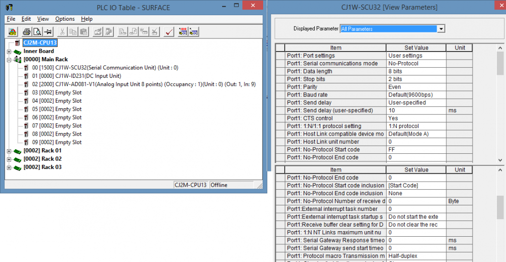
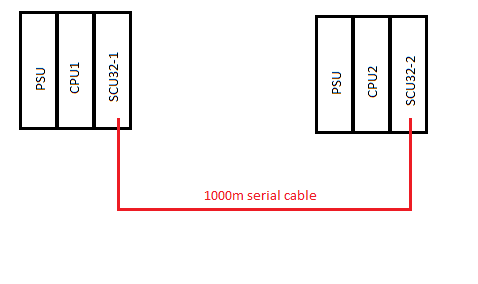
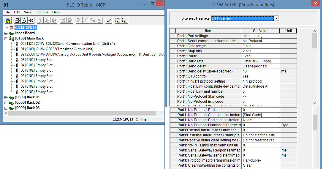
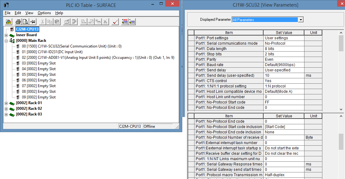
Surface rack - CPU1 ( CJ2M CPU13) + SCU32 (unit0 port1, 4 wire & terminating resistance on)
MCP RACK - CPU2 - CPU2 ( CJ2M CPU13) + SCU32 (unit1 port1,4 wire & terminating resistance on)
Connection via 2m twister pair
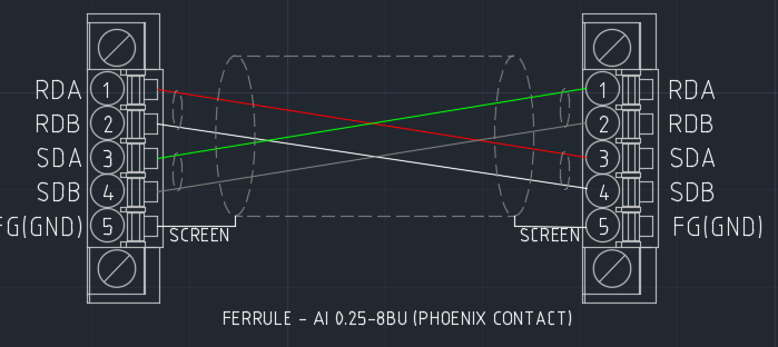
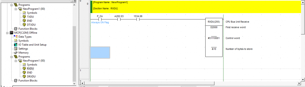
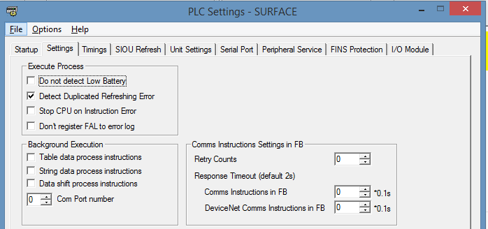
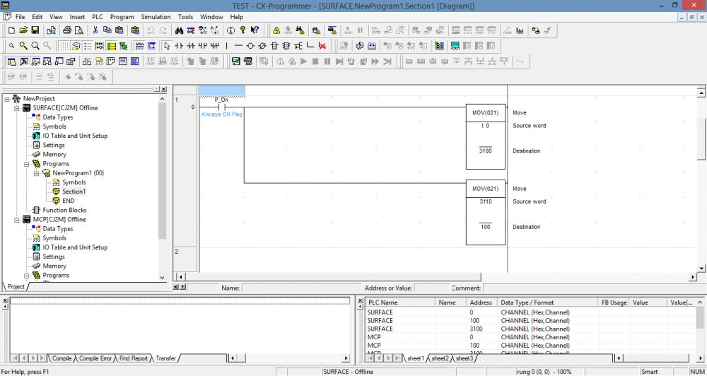
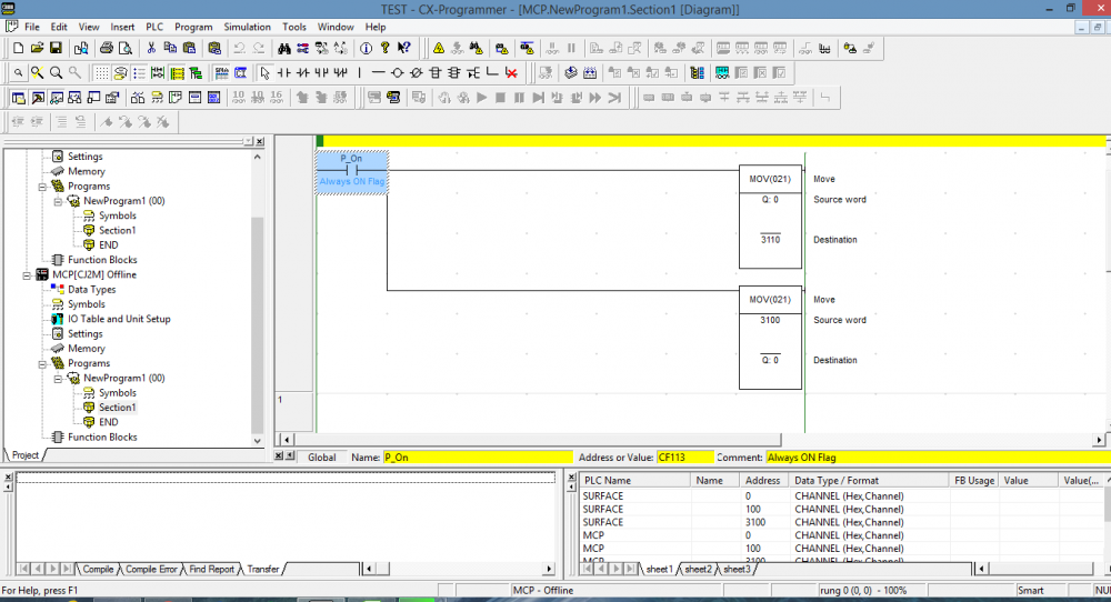
Wiring, setting and program as shown in pic.

-
hi ,
i have some issue, I tried communication between two SCU32s. But the RXDU is not updating constantly.
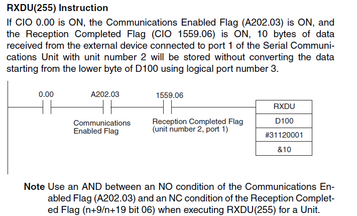
I have used the below ladder diagram. Is it correct? ( the note says NO of A202.03 AND NC of n+9 .06, but ladder is different?) No i am confused.
Also what is logical port ( "3"in the control word#31120001 ) and what is the purpose.?
-
thanks a lot
-
HI ,
I am doing on the memory adresss allocation now and i would to check whether the Wxx.xx memory can be transferred from PLC to PLC. Or should i move to D and CIO memory?
thanks a lot.
-
Thanks a lot gt support
thanks a lot.
-
Thanks a lot micheal,
Does"no protocol' work with 1000m cable?
Do you have any sample code or video?
thanks a lot.
-
thanks michael.
-
thanks alot
-
hi gt support,
Thanks a lot,
Yes. I have the SCUs. SCU32.
Ok. Do we need an adaptor for serial port to rs485 if am using the serial port in CPU?
If we go with SCU-SCU, can i use HOSTLINK?
-
hi gt support,
Thanks a lot,
That was the initial plan. But we have to use CPU serial port for HMI.
That is the reason we are planning to add SCU32. Which Protocol would be the best to use to connect two SCU32 via 1000M
-
HI ,
Thanks a lot for the reply & help on previous topic.
Now i setting up a new system with 2x CJ2M CPU13 and 2x SCU32 and the connection via 1000M RS485 cable.
May i know the best communication to use for the serial communications?
Regards,
TJ SHARON.
-
thanks a lot
-
I am using 2CPUs. CPU1 is physically connected to ID231 , and CPU2 is connected OD232. I tried to connect them via serial comm ( CPU1 as master and CPU2 as slave) and connect laptop to CPU1 for programming. when I went online, CPU1 detects ID231 ( 0000) which is correct, but CPU2 detect also ID231 (0000) . i tried to change manually the slot , but shown error while uploading.
I connected laptop to CPU2 and tried to get i/o info online, then OD232 detected.
Any idea why OD232 wasn't detected while connecting CXONE to CPU1 and two CPUs are serially linked.
-
hi
Thanks a lot gtsupport.
Do you have any sample program.
( sorry , i dont have that much experience in PLC linking).
-
Hi all,
My serial cable as attached pic.
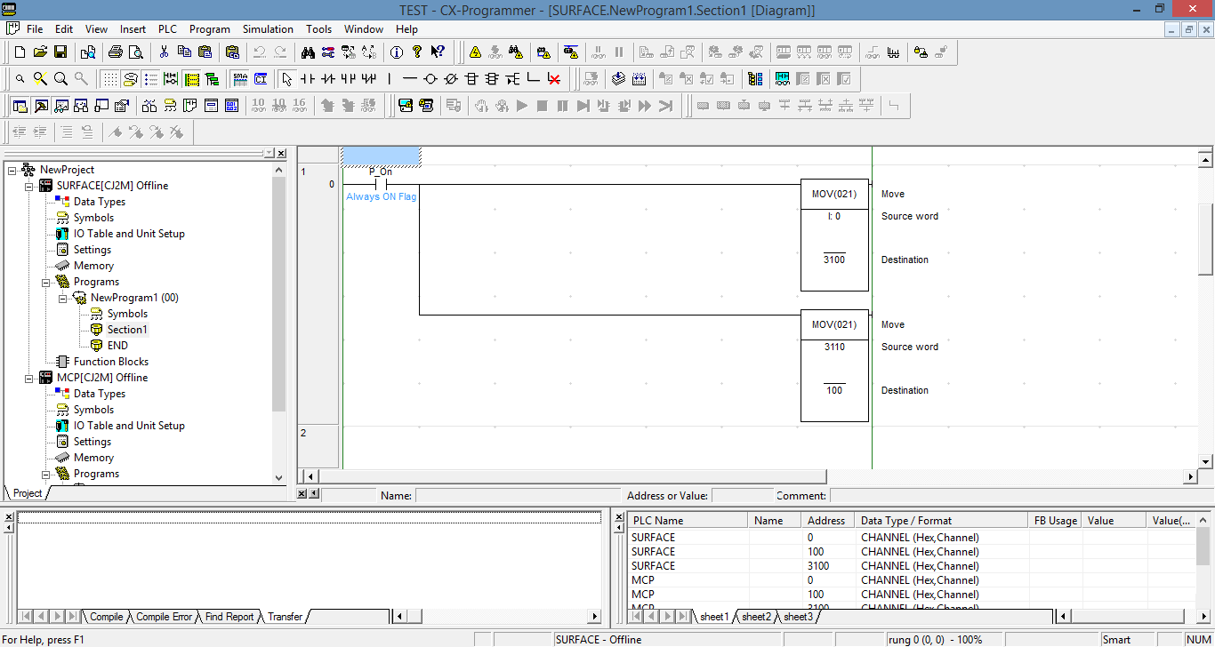
I used this program as below.
But when i use simulator i can see hexa output in 3100 & 0000. But when i go online, i cant see the output on 3100.
My objective of this project is to give some inputs in cpu and get the output from cpu2.?

-
As i said i am using 2x CJ2M cpus.
I set 1st one as master and second as slave connected via serial cable ( wiring as per the manual).
how can i check whether they are connected or communicating?


OMRON CJ2M-SCU32- RS485 Connection to gyro compass
in CX-Programmer
Posted · Edited by T J SHARON
hi all,
I am using SCU32 ( unit1, port2, 2wire and termination OFF) to get the RS485 data strings from the compass with setting 19200bps, 8 databit, 1 stop bit & No parity.
I can send the TX string ( 01 03 00 01 00 03 54 0B) from D100 memory and write the Rx data to D2000 (01 03 06 xx xx yy yy zz zz CC CC).
But the whenever the there is no RX data, The TXdata bounce back to RX. (refer to video, d100 is TX, D2000 is RX).
I also tried wth SCU32 termination resistance ON. Same thing.
I am not sure what is missing. Should i use different logical Port for TX and RX ?
EDITED:
Just tried another scenarios
1) removed the connector and tried , D2000 - was written the TX values
2) Disable the RX changing LD from P_On to P_Off. D2000 - was written to #0000 0000 0000 0000
I am not sure what is happening., Open connection also TX data bounce back to RX
Appreciate all help
Thanks a lot
video1.mp4