
.jpg.ab4bdacbd75415ee4a44ee0400895a6a.jpg)
Mitsm83
MrPLC Member-
Content count
62 -
Joined
-
Last visited
Posts posted by Mitsm83
-
-
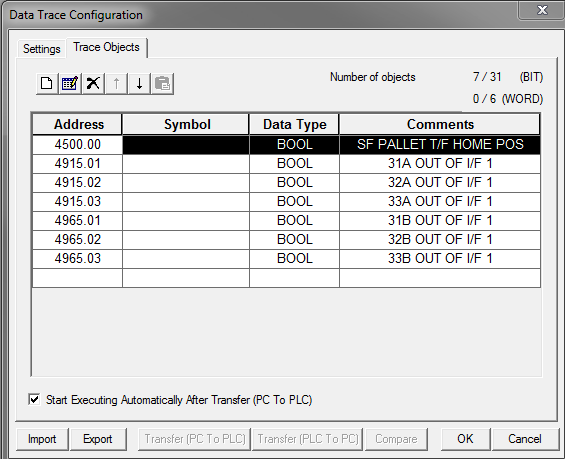
Lets say I worked in a factory that made multiple models of parts. I need to run data tracing on the off shift due to certain models only running on 2nd and 3rd shift. I want one data trace to capture one group of bits at Model 1, Then reset the Data Points and run again for Model 2, Model 3 and so on. So the Bits that I am mapping with the trace need to change.
I can change the trigger easy enough with my program.
I see in the manual the CPU has a "separate memory area" for trace settings.
Can this area be accessed from the Program so I can set my bit addresses to monitor to a word or E_?
See attached pic for clarification of what I aim to change through the program.
-
I may be barking up a tree here, just in case any one reads this later... here is the solution.
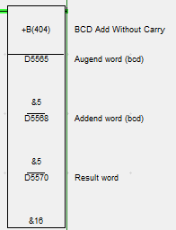
Separate out the digits by BCD command into 1 register then use 3 MOVD commands with control words of #0002 #0001 #0000 into individual words.
Now I have my digits in the 0 digit of individual BCD words..right.
Then MLPX(Decode #0000) individual words into CIO.
It makes a complicated "Variation" matrix that no one will understand but me....
Maintenance is going to love it haha... ah probably ought to just write it the long way.
-
Hello,
I am stumped on what to do to simplify some code I am working on. CS1H CPU.
I will try to explain what I am going for here.
Currently there is some code with a bunch of compares that I have to add "Variations" to. It basically says...
D100=110 ---OUT 0.00
D100=115 ---OUT 0.01
D100=118 ---OUT 0.02
There are currently a bunch of these lines with a bunch of different "variation" values turning on bits.
I know there has to be a quick way to do this so future addition of "variations" 112, 113, 127... doesn't mean going in and adding individual lines or rewriting it all to line up.
The instruction I mentally picture but cant find outputs a bit based on the value in D100.
A bad example of this would be if D100=12 turn on 0.12 but if D100=23 turn on 1.06
I hope I explained this well enough.
-
The +B Sets D2255 to a BCD value. Decimal to BCD 10=16. Hope that helps.
 1 person likes this
 -
I am sure you got it from the other posts but I like to share how I remember it.
Take the 'K' value times 4. You are basically making a register out of the M coils.
So,
K1M400 would be 4x1=4 M400-M403
K2M400 would be 4x2=8 so M400-M407
K4M400 would be 4x4=16 M400-M415
K8M400 would be 8x4 so M400-M431
And so on.
-
We usually try to send one of the regular programs that is from a machine close to what the builder is designing. So if its a machine that is attaching and torquing widgets we will send a copy of one of our current widget torquing machines, we just strip out all the network address and stuff like that. Confidentiality contracts handle all the proprietary stuff.
I suppose if you had a lot of similar machines that you needed like a press shop or something, then you could make up an example program to send every time.
-
We use a set of standards that "lay out" the programming. Usually they will request a sample program. We provide some spread sheets that lay out the address map and flow of the program as well of how we want it structured.
As a small example we would say you have to use M1000-M1999 for anything that goes to a remote device like cc-link or Melsecnet an so on... M3000-M5000 for alarms These are not the actual standards just an example.
Keeping all of our programs uniform help to make troubleshooting and editing easy because you can look at an address and instantly know a lot about what it is from.
-
I am using MX sheet version 2 to gather some PLC data.
All is working great but I decided I wanted to change the Automatic Save settings and it wont open the window.
As in I click the Automatic Save Icon in the sheet and nothing happens.
Same thing if I start a new sheet and on all the old sheets.
Thanks,
-
12 hours ago, Akahige said:Mitsubishi came out with a tech bulletin on this (R72-141-SLSASG-007). It is available on their website but here is the copy I have downloaded:
TB - iQ Works Navigator Exporting GXW2 Project Procedure.pdf
Nice find!!
1 person likes this -
4 hours ago, Paolo_911 said:Much thanks! And WOW you have a fantastic memory, bang on!
I wish, I just set up a drive on CC-Link so it was fresh, I used SW480.0 but don't ask me that next week!
PS I checked myself in the manual I linked before posting just didn't remove the "If memory part of the post" :)
-
Here is a link to a manual for the QJ61BT11N. See Appendix 3 SB and SW, this will have all the special relays and special registers that contain that info.
If memory serves me right I use SW80 (+ your head address) it is the data link status of each station as in SW80.0 is status station ,1 SW80.1 is station 2 and so on.
-
I'll second the Honda Plant, HCM.
Check out job 2016-1433
Not that I would know or anything but Honda is a great place to work. Might be a good foot in the door position for you.
-
I feel your pain on this one. I have a similar issue and was pretty much told to rewrite it...
I am looking into upgrading the Q CPUs to R CPUs then use Q to R racks when you convert the code over you can untangle the navigator project, or so I am told. You can keep all your I/O , pretty much just costs the R CPU and accessories price.
I am sure there are others on here who know more but that is what I am looking at.
-
You can make user created ones as window screens and set them to be used here. I have not done in but have seen it on a project someone else made.
-
So, I am not able to find a problem here. Hopefully someone else can help.
isengineer, if you see this and do not mind doing so post the symptoms you had sent to me that may give a better idea of where to look for others.
Good luck
-
I hope I am not doing your homework haha.
While I think you may learn more from trying it until you figure it out here is a EXAMPLE project. Do yourself a favor and do the boring online training ( Boring online Training ) I went down the road your on and I wish someone would have made me do this at my start.
You can use it to get an understanding of what you need to do. What Akahige wrote is good as well and should give you a basic concept of what you need but just in case I put this together.
Turn on comments and statements.
To run the simulator go to debug in the top bar then click Start/Stop Simulation. You may have to click stop then reset then run on the pop up it stays in error. This sim is a good way to practice without loosing a finger. Of course you will have to toggle (Shift+Enter) the liimit switches when using the sim.
2 people like this -
Not positive I can help but can take a look. I have a little experience with this.
Are you able to post your projects PLC and VFD?
More details on the problem you are experiencing as well.
-
Sounds like you may have a bunch of mechanics and you need a tech.
A way I have seen used to help pick the people you want is to just ask about three times they had a problem and solved it to return to production.
1. Electrical Problem
2. Hydraulic or Pneumatic Problem
3. Mechanical Problem
You can use the answers to get what you are after.
Asking if they are good with computers or if they like using them is another question that can weed out the more mechanical guys.
-
My easy way of remembering how many bits the "K" is controlling is just take it times 4.
Example;
K2M0 2x4=8 -M0-M7
K5M0 5x4=20 -M0-M19
K8M0 8x4=32 -M0-M31
2 people like this -
It can be hard to answer a question like that with out being there to see the set up as I can not simulate the limits easily.
How I usually get a start in doing any sequence is to write it down in a some what logical way. So then I know what it needs to do and kinda how the PLC would do it.
I might start that task by writing something like this, then trying to write code to do this may be easier.
Sequence condition (L0) sets on Cylinder Extend (Y30).
If limit 1 (X10) is reached for one second (T0) Cylinder Extend (Y30) will be reset and Cylinder Retract (Y31) will be set.
If limit 2 (X11) is reached for one second (T1) Cylinder Retract (Y31) will be reset and Cylinder Retract (Y30) will be set.
E-Stop (L1) will reset Y30 and Y31. You MUST include a way to stop the sequence even for your own training purpose you must be able to stop it preferably kill the power to the solenoids and a logical stop.
1 person likes this -
My rep knew nothing about them so must be a Europe thing.
I was actually just clarifying a question asked by my IT people. I am glad the answer was no, I think they are rounding up and locking down anything windows based.
I would hate to half to ask permission to make screens that do stuff they know nothing about lol.
-
Info for the Archives;
No they are not. GOTs are not windows based in any way.
You can run GOTsoft on most windows based PC though and get a Win based Mitsubishi HMI if need be.
1 person likes this -
GOT Experts,
Any one know if the Mitsubishi GOTs are windows based?
I am thinking I have seen thaat they are but can not find where I got this info from,
Thanks a million,
-
You can sometimes do a remote reset in GX works2. There are a few ways to do remote operations.
Go to the online drop down and select Remote Operation then you will see some buttons there you can reset from.
Also if you go to Online/Read From PLC and drop down the related functions at the bottom of the window you can do remote operations from there as well.
Or its in the system monitor i think as well take your pick. LOL
CX Programmer, CS1H, Data Trace Multiple Data Sets?
in CX-Programmer
Posted
A fellow Engineer offered the following solution.
Have a common Data Set.
So all the Trace Objects would be the same Example 0.00 0.01 0.02... and so on.
Then move the data points I need to trace in to that area based on the model.
Model 1-----| | 4915.01--------(0.00)
Model 1-----| | 4614.01--------(0.01)
Model 2-----| | 4913.01--------(0.00)
Model 2-----| | 4917.06--------(0.01)