

markyspicer
MrPLC Member-
Content count
79 -
Joined
-
Last visited
Posts posted by markyspicer
-
-
Hi Moggie!
Thanks for the reply. I'm able to do this before by pressing button in order to send email. My concern is that if an alarm has been triggered(from the plc), is it possible to send an email(wincc flex) to notify the user? Because as far as my knowledge you can "SendEmail" from the properties of a button. What if I don't want to ise button instead when alarm in on it will automatically send email(configuration for alarm to send email still my problem). hehe
-
Hi,
I have some concern regarding sending an email automatically when an alarm trigger(High, Low Level Alarms - Bit), Is this possible for the software?
Thanks for any reply.
-
Hi @pfort!
Thanks for the reply!
Is it OK to Work Online even though we don't have a back up program?
-
Hi!
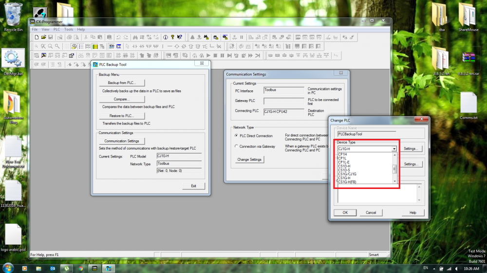
I have this CQM1 CPU21 plc running but the problem is that I'm not able to communicate using CX Programmer V9.5. Under the "Backup PLC" section, the drop down list for the specified PLC is not included. Is there any update/software to be use in order to communicate the PLC?
I have "USB to RS232 Cable" that I have been using for different PLC, I also have this OMRON CQM1-CIF02 Interface Unit that is not also working upon communicating the PLC. I'm thinking that the software itself has a problem or needs an update.
I hope someone can help. Newbie here in OMRON PLC.
Thanks!!!
Marky
-
Hi,
Is there any way in order to monitor both PLC(GXworks2) and HMI(WinCCFlex) using only 1 port from the PLC(FX3U)?
I have tried it but I'm not able to communicate the other application(one at a time only).
Thanks!
-
-
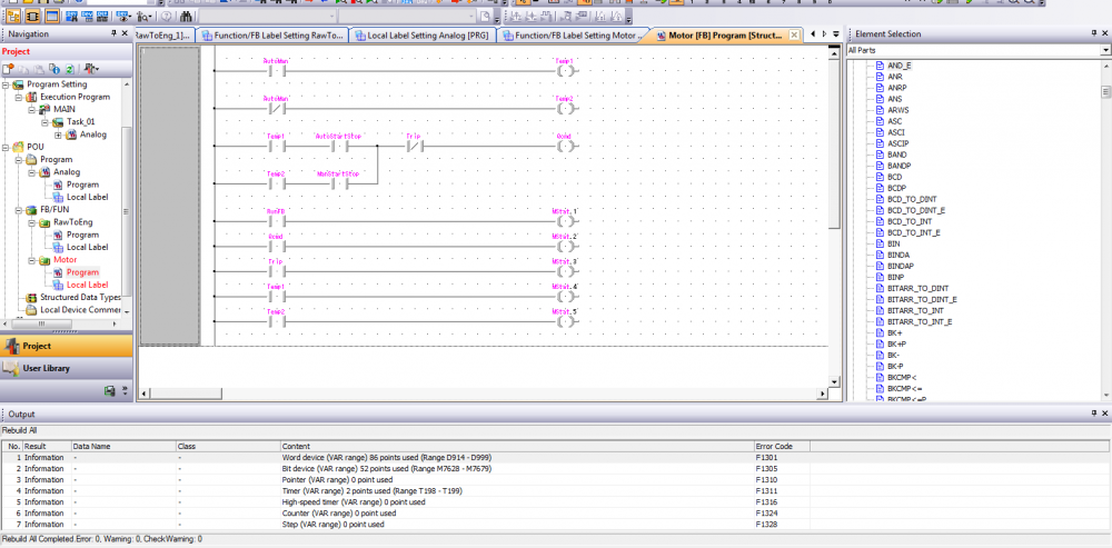
I see, I think this is the main cause of the error.
I'm trying to implement WORD data into BITS. Can you show me example of data manipulation for INT(or a table for data addresses in mitsubishi)? like (MW10 can work with M10.0 ...... in siemens)
-
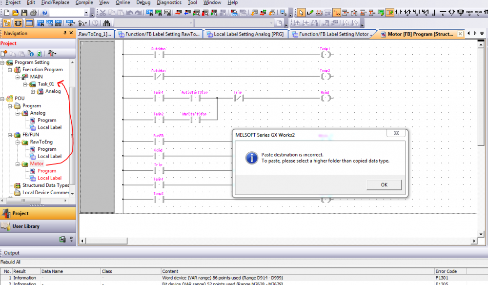
i try to drag into the Task_01 but an error occur. I'm using FX3U PLC.
-
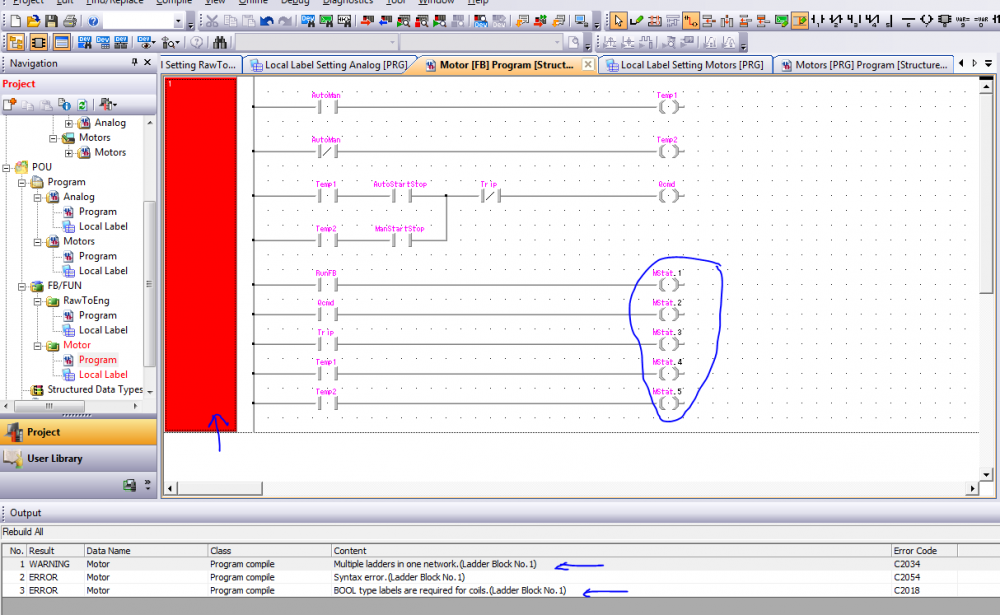
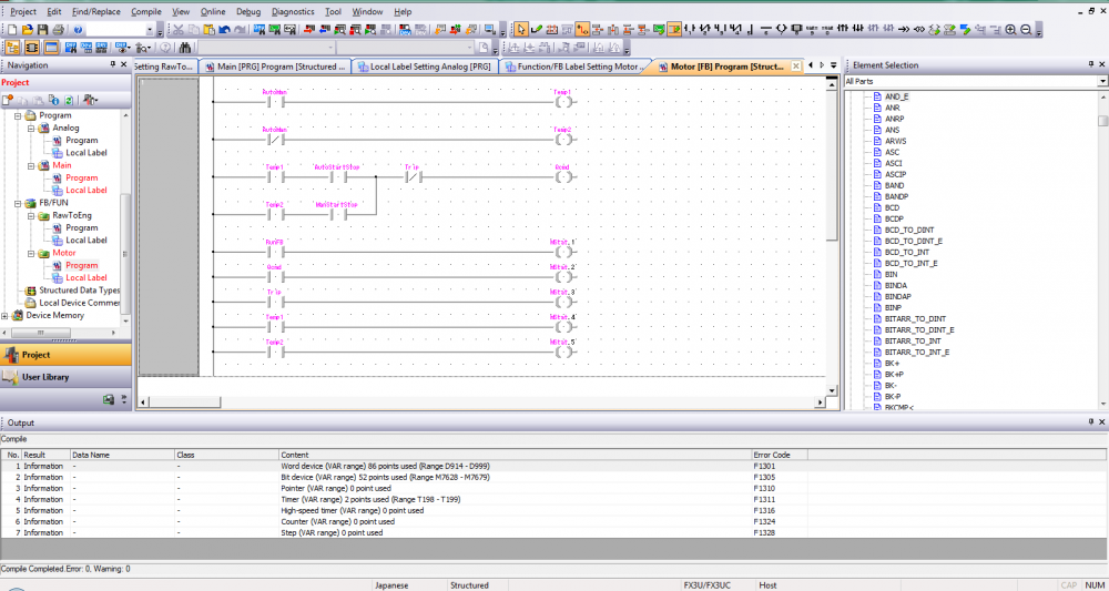
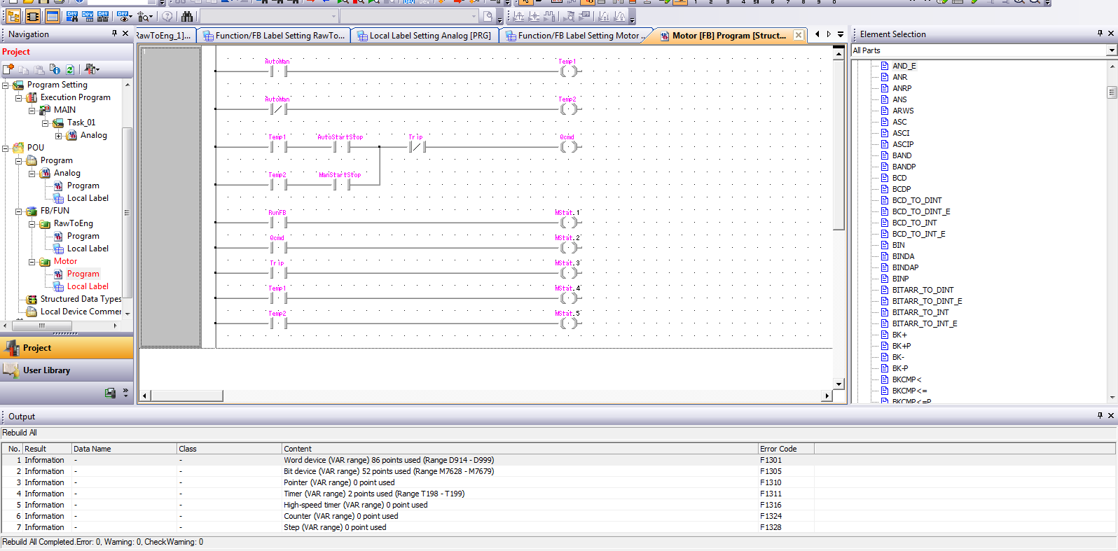
In my Execution program task only the "Analog" block included. i try to delete first the "Main" block since it doesn't contain any program yet. but still the "Motor FB" is in red state even after compiling the whole program while the "RawToEng" block which is the same Function Block with "Motor" is working fine.
-
Hi!
Anyone can help regarding this issue. I'm not able to monitor the Motor Block that I have created. there's no error either in the output screen but i'm thinking what is the cause of not running in the simulation which shows the Motor Folder RED even it was compiled.
thanks for the help!
Note: I'm new in mitsubishi.
-
Try to check here
i don't know the specification of the device, you can just simply search from here. GSD file for profibus are available.
1 person likes this -
I don't know if this one is available to their site(Schneider). If your drives are in the profibus network. you can just simply configure your network(Step 7) and add the corresponding GSD file of the device.
-
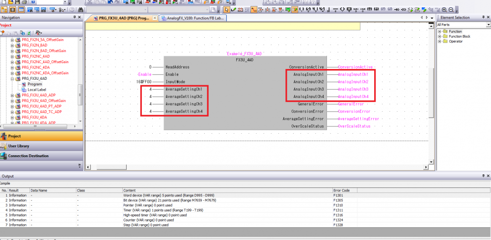
What is the meaning of the tags "iAverSaplesM1CH1......."?
I just leave mine as a default "4". Also the "RawToEng" block, this one is included into the Elements?
-
Hi!
I have the block now, the problem is that I'm not that familiar regarding the block. what am I going to address? how the block works? why there are some constant no. at the left side of the analog block? If I have 8 analog inputs to be monitored in the plc does it mean I need to analog blocks? can you guide me regarding the addressing of the analog?
Hope you may help me.
-
ok I will try.
Thanks! 🍻
-
Just now, Clear.Mind said:You need use from/to instruction for writing reading buffer registers from modules. But easy way register on https://eu3a.mitsubishielectric.com and download analog function library FX Series for GX Works2 (AnalogFX_V100.zip). This library have all you need with helpful chm datasheet. If can't register i may send you it on your e-mail.
Hi!
Thanks for the reply! I have already registered but the problem is that there is some error finding the "AnalogFX_V100.zip" file.
Can you kindly send or message the file to me?
Thanks!
-
Try this one using GSD file. Hope this may help mapping some variables.
1 person likes this -
WinCC Flexible Advanced 2008 SP3 or TIA Portal WinCC v13
-
Try to restart PLC first.
If doesn't work, if you have programming device you can simply go to the cpu's diagnostic buffer in order to identify the cause. be careful when connecting be sure to upload the program for references and backup.
-
Hi,
Anyone can help how to program a analog coming from a level transmitter? I have 8 analog inputs (2 unit of FX3U-4AD) to be read out into the plc program. how can this be possible. I'm new to mitsubishi analog. it is different from my experience(using siemens before).
Hope someone can help.
Thanks!!!
Marky


FX3U-485ADP-MB
in Mitsubishi
Posted
Hi!
I have some concern dealing with the FX3U-485ADP-MB device which will be plan to install and a total of 17 modbus devices(Chinese brand converter 4-20mA to RS485) where going to communicate. I'm new to this feature of FX3U family and I'm using GxWorks2. Is there anyone that can guide me through this device/development? Is there a program block for this like the one I have been use for analog modules(FX3U-4AD)?
Looking forward to your help!
Thanks a lot!
Marky