

Luke.S
MrPLC Member-
Content count
110 -
Joined
-
Last visited
Posts posted by Luke.S
-
-
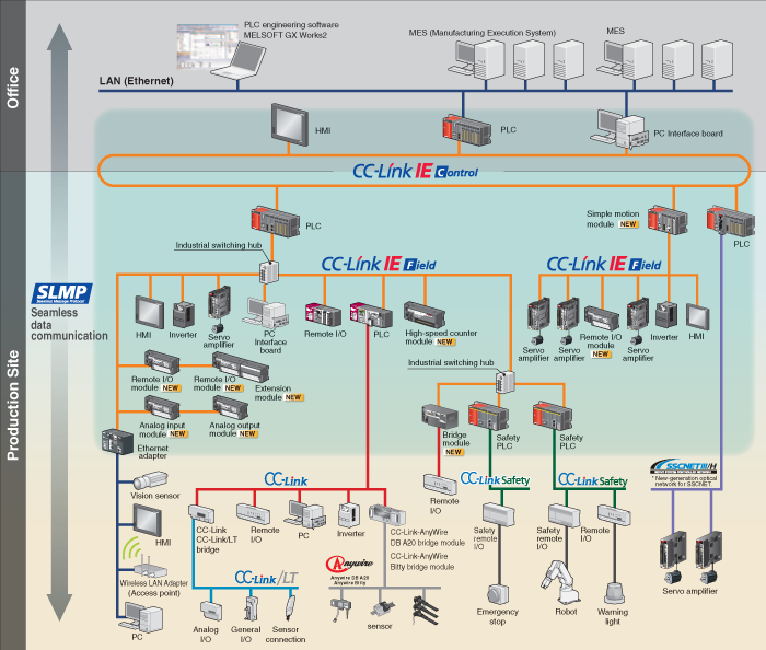
Yes. If I couldn't upgrade the A that's what I would do. Connect a GOT 1000 to the A and then you have some options to communicate with Ethernet. Some GOTs can even connect directly to a CC-Link IE fiber network. I would get a GOT2000 model if you can though. GOT1000s are being phased out.
 1 person likes this
 -
The only fiber networks I know Mitsubishi has that can connect to that gateway PLC is CC-Link IE Control or MELSECNET/H. This should be no problem for the Q. You need CCL-IE or MELSECNET/H network modules on the Q CPU and gateway. Or you can connect straight to a PC with a PCI interface card.
The A series is a problem though because it is extremely difficult to get any parts for it now, even second hand. You could use the serial port on the A to send data to the Q which can then be forwarded to the gateway. But the best thing to do would be to upgrade the A to a Q. It's relatively easy to convert the A program so it can be used on a Q and you can support the comms to the gateway. The cost of replacing would probably be small compared to the long downtime you could face if the A stops working.
1 person likes this -
Please give more details about the configuration of the current system. e.g. How many/type of modules already installed etc.
-
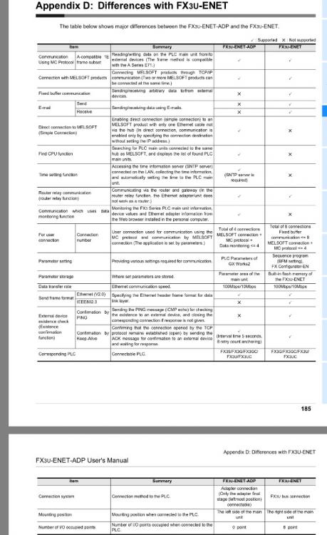
You're welcome. I don't know what your application is but this table should help you pick the right one
-
The ADP plugs into the left side of the CPU and you access it via special devices (SM/SD) which are detailed in the manual.
The ENET is connected to the external bus on the right side and is accessed via buffer memory (e.g. FROM/TO commands). You will need to identify the start I/O number of the module depending on its location on the bus.
1 person likes this -
In the button properties go to the Trigger tab and you can set the switch to only be active when a bit is ON or OFF etc.
You can also make it grey out the button when it's not available in the Extended tab -> "set the style.. for a switch in non-operating state."
-
If you just want to run a Mitsubishi rotary servo at a constant speed does it make any difference if you use the JOG command or put it into speed control mode? Or to put it another way; is there any reason you should <u>not<\u> use jog mode for routine operation?
Say you have 8 servos in a line that you just want to run at a very low, accurate speed, simply putting 8 JOG FBs in the program would save a lot of time.
You can change the speed even in JOG operation with the speed change command. The drive must be controlling the torque in the same way to achieve steady velocity as in speed control mode unless you are limiting torque or something. So what's the difference?
-
Ethernet cable is faulty
Melsec communication driver is not installed on the GOT
GOT communication settings are incorrect
QJ71E71 is not configured correctly as described in manual
IP address of GOT is exactly the same as PLC +1 (or +2 or any other number) if there is nothing else on the network. If there are other devices on the network make sure the GOT has a different IP address to all of them and is not using the same port as anything else
-
Perhaps I should point out that strictly speaking this topic probably shouldn't be in the Mitsubishi board.
But anyway, if you are adjusting the line speed to make each product get enough heating time then maybe you could just average out the current consumption of the heaters over a certain period. That'll give you the average kW usage. A kW just means 1000J/s and 1 kWh =3,600,000 J.
So for example if the heater is using an average 1 kW and the product is in the oven 10 seconds at the current line speed then current cost per product is (10,000 J/3,600,000 J)*3.21Rs.
You could display it in real time based on real time line speed feedback. Cost_PV=(((oven_length/lineSpeed_PV)*averagekW_PV)/3,600,000)*3.21
If you want it per kg then just divide that cost by the weight of the product. I am assuming that only one product goes through the oven at a time, otherwise it's a bit more complicated but that's the general idea.
-
You can see if any ports are already opened there which may be causing conflicts.
-
Do you mean 1kWh of electricity to power the heater costs Rs3.21?
If it's an electric heater you could measure the current to it with a current transducer on the line, feed that back to the PLC analog input and get a wattage with P=IV.
Then if you know the length of the oven you know how long the product was in there: time(s)=length of oven(mm)/speed(mm/s). From that you can get calculate how much of a kWh was used on one product.
-
Check the "Open" settings in the Ethernet tab of PC Parameters.
-
You can do that really easily on the GOT with the logging function. It is on the left tree in GT designer under "Project." You can set it up to sample PLC devices at set intervals or on a one shot etc. and save the log data to files (including CSV which is good for excel).
I have done this on physical GOT HMIs but I have never used soft GOT. As its running on a PC I would imagine it can save CSVs directly on the HDD. On the physical GOT you need a USB stick or SD card and to get the data directly on the PC without an "air gap" would require some software implementing MC protocol to communicate with PLC.
-
The "feed current value," "real current value" and "deviation counter value" are probably stored in d0 to d5 + 20n. Where n is the number of the axis -1.
(3 32bit values in 6 registers)
But I don't know enough about the setup you are using. You need to read through the manuals for your motion controller and look at how it's been configured in the PLC program.
-
Do you have it set to display labels and comments in the display settings?
I can't spot anything wrong in the screenshots. Maybe have a look at the compiler settings regarding how local labels are handled. Or try calling Mitsubishi support.
-
Great that it works.
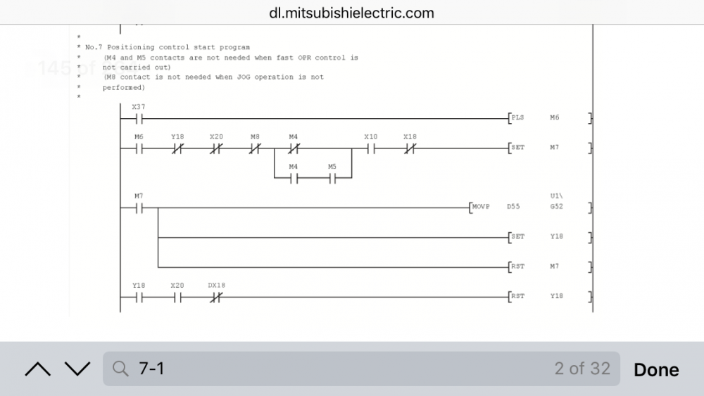
I recommend using SET/RST instead of a timer if you can. When the program gets more complicated and lots of events are going on, it makes it easier to keep track of things and make sure they don't interrupt each other.
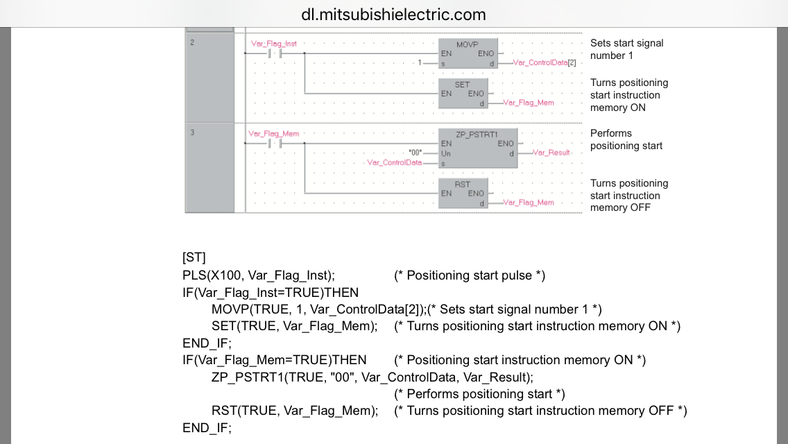
As you can see in Mitsubishi's example above, M7 gets latched on when it's interlock conditions are met. It stays on until Y18 turns on. That makes sure that another routine couldn't overwrite U1/G52 and maybe cause an accident if some other positioning started when you were expecting a HPR.
-
Go to the labels -> M+ labels in the navigation tree on the left. Are module labels registered for the fx5cpu and 40ssc-s?
If not then go to the element selection window (probably on the right) and find the modules tab. Right click on the CPU module and MCU modules and select "add labels.." and it should be ok if you recompile everything.
Make sure you click the option to register local labels when you add a FB to your ladder as well.
Hope that helps.
-
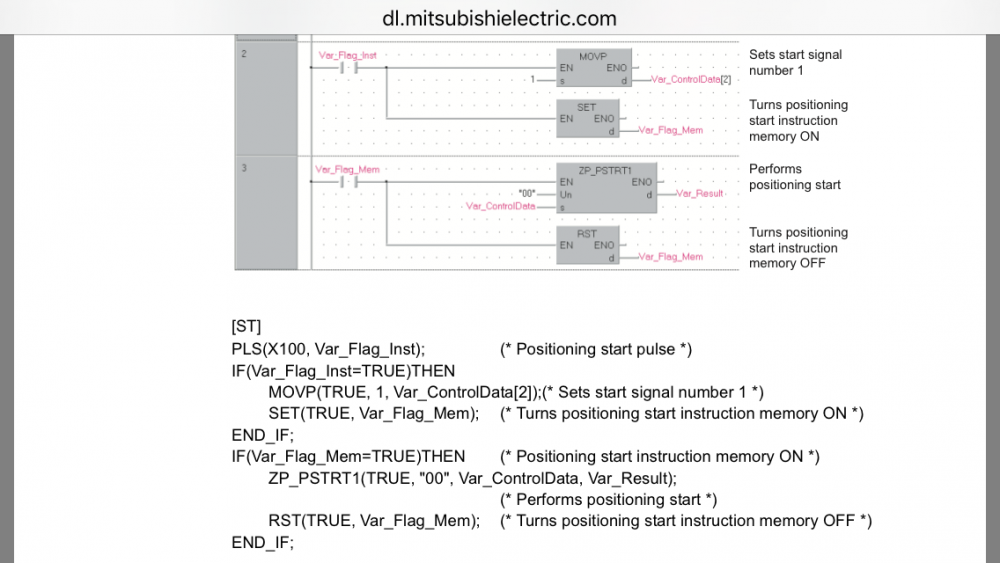
It looks like the positioning operation fails to start and you are getting error 820 to warn you about that.
Under what conditions is M161 reset?
From the code you posted above it looks like the RST comes immediately after the positioning start command. In that case it's likely the drive does not have time to respond within one scan of the PLC. The [ZP.PSTRT1 command is turned off before it can complete properly.
Try this:
*SET M161
*when M161=ON, execute OPR as you are but don't RST M161 yet
*RST M161 when M161=ON AND positioningStartOK signal OR positioningStartError signal
Also make sure no other commands can be issued to the axis at the same time as M161 is ON.
In the programming example, I think X20 is the startOK signal and X18 is the startError signal.
EDIT:
Just got a chance to have a proper look at that zp_pstrt instruction and I think the problem is that you MOVP the position no. at the wrong time. Do the MOVP 9001and SET M161 when M160 is pulsed. Then when M161 is ON, execute zp.pstrt and RST M161.
Hope that is more helpful sorry.
-
drforsythe, thank you for your reply.
I suppose I just have to learn from this experience (like with many other things I learnt are harder to change later) and try to get a tentative specification out early on. Even if I don't get any answers, it might get the ball rolling.
What makes things tricky for me here is that I'm younger than most of the people I'm working with on this so I have to watch how much I assert myself.
-
When using an auxiliary piece of equipment or a retrofit on, for example, a production line, who's responsibility is it to define the I/O specification between them? The designer of the software in the slave equipment or the administrator of the software in the line master PLC?
I am programming a servo system which works in sync with a line. The only input I have to start and stop is an "auto_run" bit from the master. Because there are many possibilities regarding what the servos are doing at any one time and it's over an industrial network, I requested the "Stop," command to be a handshake format. I want to send an acknowledgement back to the master upon actual "zero speed," feedback from the drives. The response was that it is my responsibility to sort it out on my end.
I got it to work with just the "auto_run" bit falling edge but I feel like this is the not the most professional way to do it. What if the timing changes or the equipment gets reassigned to a different process in the future? Is it not normal that I require certain I/O to be in a specific format so I can make sure my code is robust? There seems to be a lack of commonly accepted best practice in the PLC field.
-
I'm pretty sure you need to set the "convertion enable" bits for the channels you are using with a TO command if you haven't already.
There should be an example of this program in the manual for that module if you google it.
-
Yes. ~9046 pulses are required to move 1mm. It might not actually work that way though. You might need to tune the drive to improve steady state error, the paper could slip on the roll etc.
-
Yes that is pi π.
The circumference of the roll is pi x roll diameter. The circumference = feed of one roll revolution.
Sorry if I misunderstand you but do you mean 695.5 is the circumference?
-
The J4 series have a 22 bit encoder. That's 4,194,304 pulses in one revolution of the motor.
The motor rotates 1.5 times for one rotation of the load. That's 6,291,456 pulses.
The load has a feed distance per one revolution of 3.14159..x695.5 = 2184.977691mm (assuming you gave us the roller diameter above). Therefore the number of pulses required to feed 1 mm is 6,291,456/2184.977691=2879.
Take your target feed value in mm from e.g. HMI and multiply it by 2879 (signed bin32) and send that to the drive.
1 person likes this


CC-link no digital output
in Mitsubishi
Posted
Sorry if this is sounds obvious but I just want to get an idea of where you're at. There's 2 assignments:
1. Assignment of the start IO/ unit no. of the master module to interface with the Q CPU via x or y bits and buffer memory register (in PC Parameter)
2. Assignment of local auto-refresh devices to remote devices Rww, Rwr, Rx, Ry so you don't need a program to send everything via the buffer memory mentioned above ( in Network->CC-Link Parameters)
The module assignment for No.1 will take 32 xy points (2 channels) and this depends on where the module sits in your rack configuration.
Above you mention 128 points from 0D00. Does this refer to No.2 the auto refresh assignment? Is this specified for both Rx's and Ry's in your CC-Link settings?
What are your cyclic settings for the remote device station? Are enough refresh devices assigned for this?
Because no error lights are showing I think your wiring and settings on the remote device are fine. Just one of the above settings aren't quite right, most likely No.2.