

triee
MrPLC Member-
Content count
22 -
Joined
-
Last visited
Posts posted by triee
-
-
The ladder in plc
M8000---------------------------[mov d10 d0 ]
Its mean i read d10 value in comtest pro ?
-
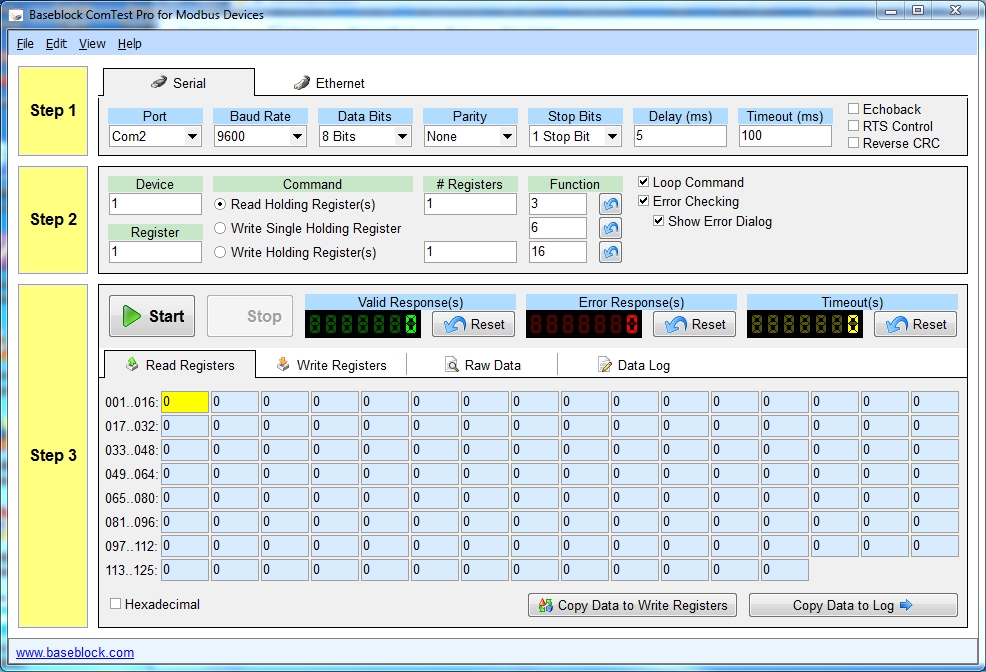
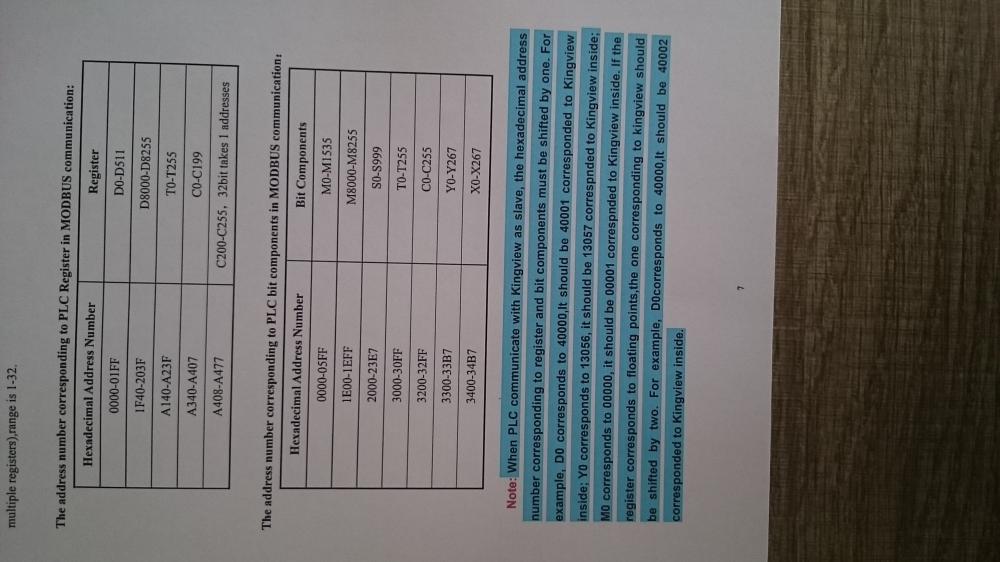
17 hours ago, Wasan said:@triee You need to scan Modbus address first. For your attach manual it shows that for D0 - D511 you need to use Modbus Address 0 - 1FF (40000 - 40511) Then you should config Comtest BB Pro as shown as image attached. Then Change value on D0 or D1 then check what data do you receive.
 .
.
What about the x and y can you give me clue setting in comtest pro ?
-
You can install gxwork2 new version is include gx developer
-
On 8/24/2019 at 9:05 PM, DanW said:I'm not a mitsubishi guy, I'm a Modbus guy, so I can't comment on your ladder.
Several observations.
CRC error
99% of Modbus is half-duplex "2 wire RS-485" which means that handshaking is not used. That's why the "handshake control" feature should not be checked (first graphic, upper right), because 2 wire RS-485 has no provision for the RTS signal (a separate pin on RS-232).Checking "reverse CRC" is probably why your 3rd graphic shows an invalid checksum. If the checksum bytes are reversed, the the checksum is wrong. Uncheck the "reverse CRC" feature.
Not a valid Modbus reply
In the first graphic, the single byte response, A7, makes no sense whatsoever. A valid Modbus reply message, even an error-exception code reply is a formatted message with at least 8 bytes."Read Holding Registers" or "Read Input Registers"?
In the first graphic, the "Read Holding Registers" is selected, with a Function 4. In Step 3, the 2nd byte in the message [04h] "Data Out" message confirms that the Modbus message is requesting a read of the "Input Registers", which is what Function Code 04 does.Input Registers are a different set of registers than Holding Registers in a slave. Some few slave devices map the same information in the Input Registers to the Holding Registers, but many do not. A source of confusion is that Input Registers are identified by the leading numeral (3)xxxxx, whereas Holding Registers are identified by the leading numeral (4)xxxxx.
So Function Code 03 (read Input Registers) reads the (4)xxxxx memory area, but
Function Code 04 (read Holding Registers) reads the (3)xxxxx memory area.The graphic shows what I consider a misrepresentation because it allows Function 04 to be incorrectly associated or identified with Holding Registers.
The bottom line is that the query is polling the slave's Input Registers, (3)xxxxx, with Function Code 04, and if that's what
you want, fine; or maybe you need to poll with Function Code 03 instead if you need to poll Holding registersUnreadable graphics
I'm sure there's critical information in the graphics of manual pages that you posted, but it's your problem and if you can't take the time to format the graphics so they're readable, you can't expect readers to jump through hoops to do so.
Who's Master, Who's Slave?By definition, Modbus RTU Masters can not communicate with another Modbus RTU master.
The text about connecting to weinview hmi - most HMI's operate as Modbus master so that actions like pressing a soft switch on the HMI immediately sends the status change to the PLC without waiting for a PLC master to poll the HMI for changed states.
I had assumed that the first set of 3 graphics were Modbus Master setup pages for the Fx2n PLC.
If the Fx2n is a Modbus Master, can the Weintek HMI be a Modbus slave?
Parity
The rule for serial RS-485 communications (which is one of the hardware comm links used by Modbus RTU, the other is RS-232) is that the parity settings for all devices on the link MUST be the same.The Modbus Spec says that devices MUST have Even Parity, but there are no Modbus Police to enforce the specification, so occasionally there are vendors who use only No Parity. But most allow a choice of even, odd, or none Parity.
But you have to match the parity settings for the Master and all slaves or you have garbage network that won't work.
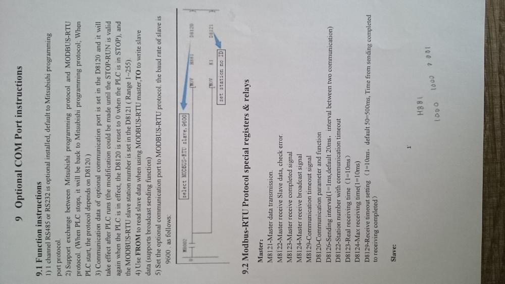
Hmi weinview as master and plc as slave , the graphic show i used converter 232 to 485 in my pc side and the plc side direct 485 from plc board
20 hours ago, triee said: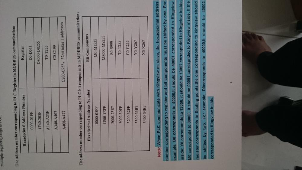
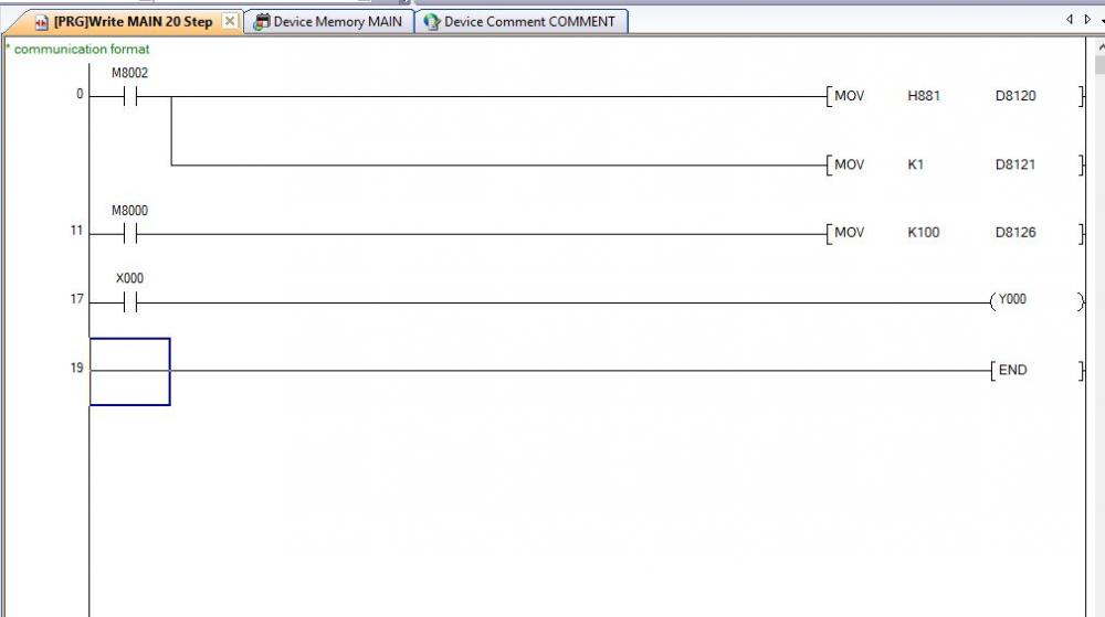
Can you give me the right ladder?
-
M8000----------------------------------------[ mov D10 D8030 ]
You can write value in d10 the out put voltage will send to DA , register for DA in your plc (D8030) the example
-
Can you give me the right ladder?
-
16 minutes ago, triee said:
-
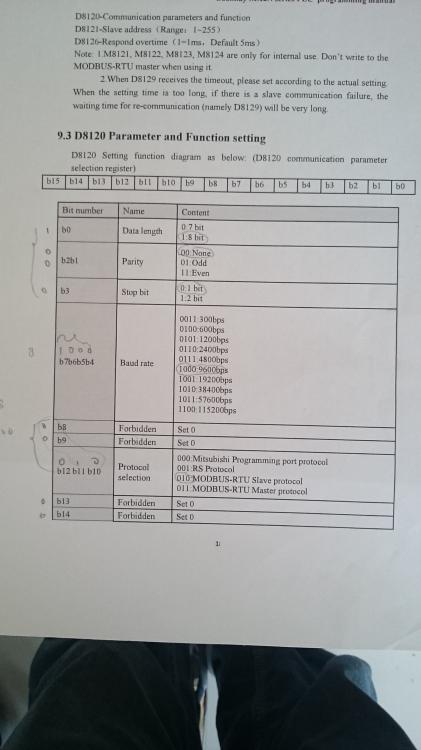
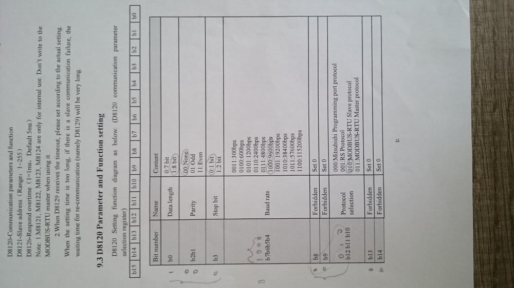
On 8/26/2019 at 9:10 AM, Wasan said:@triee For use FX PLC to Modbus Slave you should check that how data from PLC (X, Y, M ,D) mapping to Modbus Address (40001, 40002, 40003, etc). Please shown us your model and link to manual to check how to setting it.
-
18 hours ago, Wasan said:@triee You should uncheck at RTS control and Reverse CRC. Then check communication format to use Modbus. Which RS-485 communication module that you use. Do you use chinese PLC board?
The modbus rtu must be even parity ?
-
can give me example ladder i want connect with weinview hmi
-
Here the data
-
16 hours ago, Wasan said:@triee You should uncheck at RTS control and Reverse CRC. Then check communication format to use Modbus. Which RS-485 communication module that you use. Do you use chinese PLC board?
Can you give me the right example ladder
-
9 hours ago, Tech Fred said:The response is a single byte. You should be getting back a response with 10 data bytes 3 header bytes and 2 trailing check sum bytes. Similar to the following:
[01h] [03h] [0Ah] [00h] [01h] [00h] [02h] [00h] [03h] [00h] [04h] [00h] [05h] [24h] [CFh]
Can you give me example ?
-
16 hours ago, Wasan said:@triee You should uncheck at RTS control and Reverse CRC. Then check communication format to use Modbus. Which RS-485 communication module that you use. Do you use chinese PLC board?
Yes , what do you think any problem with my ladder?
-
i hope some one can explain what the problem


-
Anyone can give me ladder for hmi and fx2n modbus?
-
On 5/7/2015 at 4:43 PM, Love PLC said:It works. Thanks! :)
Can you share the ladder in zip ?
-
can somebody helpme how to connect mt8071ie with fx2n chinesse plc board with rs485 2 wire with modbus protocol
-
On 24/5/2013 at 11:12 AM, Fluke. said:Hello . ihave the folowing situation. i bought a granit cutting machine with fx1n-40mr plc controller., i need to edit the programm but its password protected. the original owner of the machine canot remember the 8 digit password. how can i bypass or retreive it. thanks fluke.
it possible to see the password i even can see the fx2n password protected
On 24/5/2013 at 11:12 AM, Fluke. said:Hello . ihave the folowing situation. i bought a granit cutting machine with fx1n-40mr plc controller., i need to edit the programm but its password protected. the original owner of the machine canot remember the 8 digit password. how can i bypass or retreive it. thanks fluke.
-
any one have tutorial for mc worx ?
-
i need iq work softwere where i can get it with product id i want build my scada or hmi


cant some one explain my problem fx2n modbus
in Mitsubishi
Posted
I was trying thats but still same err checksum