

electric101
MrPLC Member-
Content count
28 -
Joined
-
Last visited
Posts posted by electric101
-
-
I'm wondering if it's just something with the 1756 cards because when I add an ib8 point IO card it's just 8 bits. If anyone has an idea I'm really curious about this now.
-
I'm building a program from scratch for the first time in awhile and I'm noticing after adding an OA16 card that I have 32 bits of output data and the data type is a DINT. I'm using version 30 now and when I open some of my older programs in ver.15 I notice those 16 bit cards are SINT and only have 16 bits of output data as I'd expect. What gives, why am I seeing 32 bits for this 16 bit card?
-
Hi,
I'm attempting to convert some old Siemens workshop 505 code to control logix and i have basically no siemens experience at all and i'm confused as to how to tell what actual output card X1 or X2085 is referencing?? same with inputs.
-
Gerry,
the 8 point flex module is connected to the softlogix processor using a 1784 PCIDS (PCI devicenet scanner card in the PC) I used rsnetworks for devicenet to add the modules to the 1794 devicenet adapter and then added it to the scanlist of the 1784 scanner. I then added the devicenet scanner to my rslogix 5000 project and it automatically mapped an array of DINTS [123]
I say all of that so that you know exactly what I have and know that a lot of what you say may seem like common knowledge to you guys but I've not had 1 day of actual training on PLC's or had anyone around me that knew them that I could learn from. everything I know has been from reading online, playing with the 2 that I have in my lab and 8 months of work experience with them.
so,
are you saying that with the copy instruction I had on the valve with a length of 2 I was actually copying 2 bytes or 16 bits of the Valve001 UDT (even though it isn't that big) ?
is there anyway to stagger where the data is copied to in a DINT. like if I wanted to copy 1 byte (8bits) from some other DINT into Local:1:O.Data[1] but I didn't want it to start on the first byte of the Local:1:O.Data[1] .... say I wanted it to copy it to the 2nd byte so that I could map the first byte using XIC.
thanks!
-
Greetings,
I'm here in my home lab trying to acquire a working knowledge of UDT's. I've had to work with them in the past in large existing programs and they were a pain to track down and find out what IO they were really controlling. I have a decent understanding of what they are and I've created several to play with here using my softlogix processor and a digital flex IO rack.
My issue starts when i'm trying connect my UDT's to the physical IO. it looks like I cant use a simple move instruction (which would be way too easy and exactly what I need) I have a flex IO 8 point output. Local:1:O.Data[0]
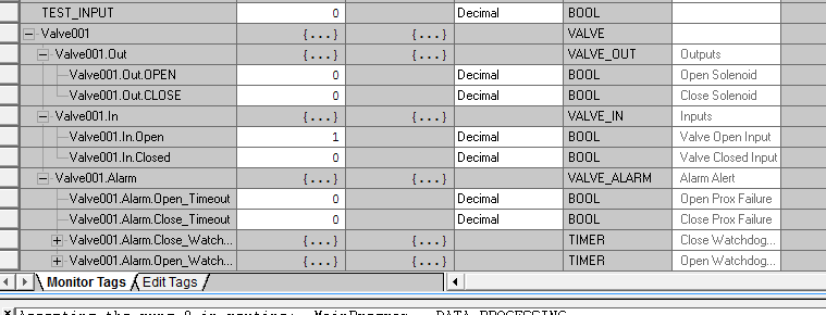
I have a UDT consisting of (see attachment)
Valve001
Valve001.Out
Valve001.Out.OPEN
Valve001.Out.CLOSE
Valve001.In
Valve001.In.OPEN
Valve001.In.CLOSED
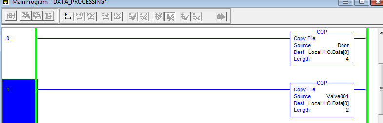
I have a copy instruction set to copy Valve001 to Local:1:O.Data[0] Length 2
that allows the Out.Open and Out.Close UDT's to control bits 0 and 1 of the 8 bit output . .... great.
Now I have another UDT setup to control lighting...
Door
Door.Out.OPEN
Door.Out.CLOSE
I want to control bits 2 and 3
I make another copy instruction in a line before the original copy instruction that states Copy Door to Local:1:O.Data[0] Length 4
but i'm really just fighting for the same 2 bits that the valve controls.... how can I control bits 2 and 3 for the door/lighting logic using these UDT's?
and that's not yet getting into having physical inputs moved/copied to the UDT input bits.
thanks!!
-
our company has done it on the 1794 without RSLINX interfacing to QNX based controller.... we have at least 100 sites with this setup. of course there is no telling how much time and effort went into making this happen.
-
thanks guys, I love learning cool stuff like that.
-
-
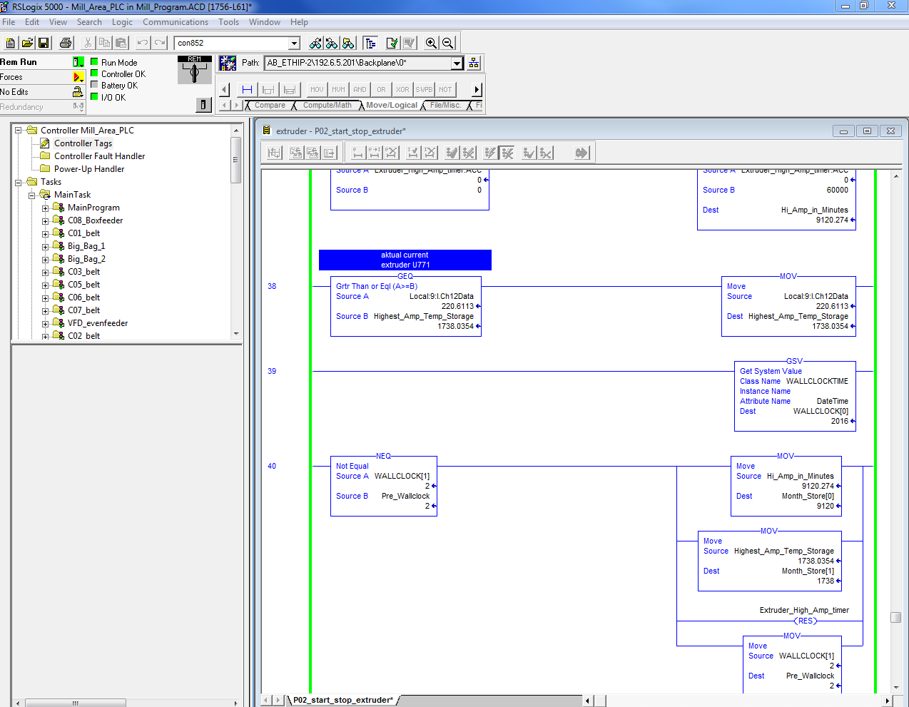
Thanks nehpets,
that was just the inspiration I needed I think. I didn't understand the adding 1 to an index but check out what I have now, I think it gets done what I need... i'll just have to extract the data each month before the rollover.
thanks again
-
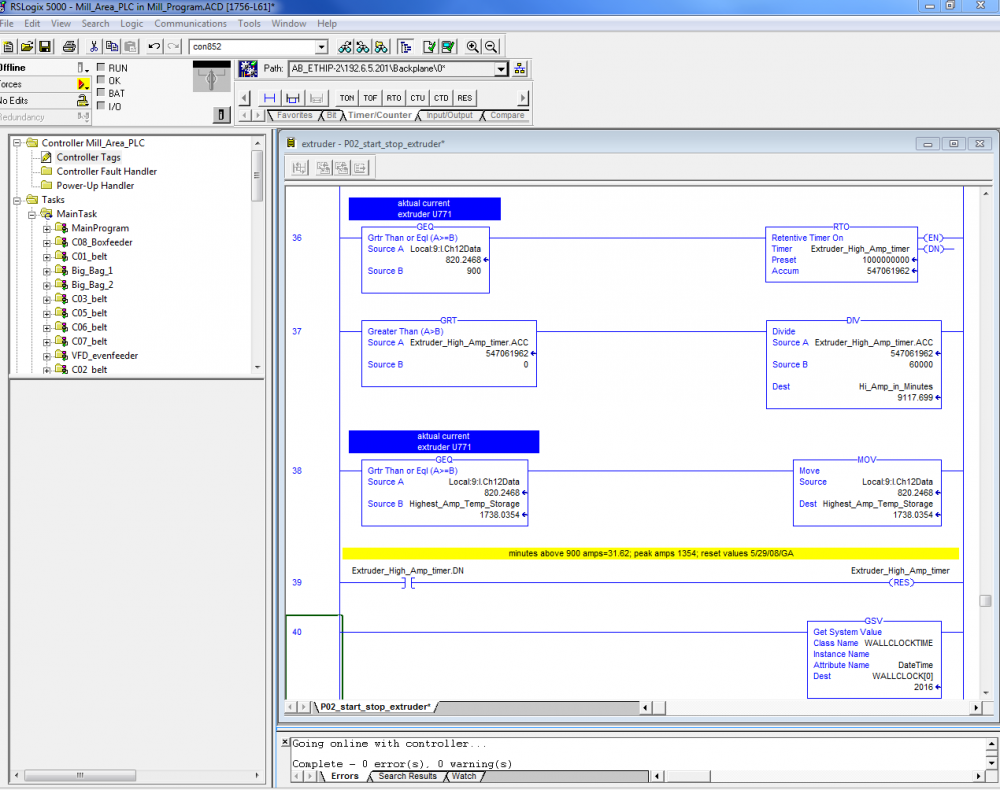
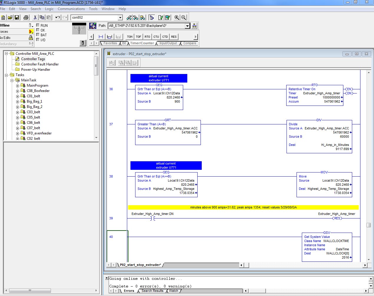
here is an image of the part of the code im working on.... this was all designed and modified years ago by germans and the only modifications I've made so far is adding the system clock on line 40
-
Im working on a way to reset a RTO (retentative timer) that counts how long a motor runs above alarm current levels and keeps a record of the highest current recorded... currently it just counts forever but
I want to reset it each month... and to possibly move data into monthly registers to evaluate and compare. I have my GSV setup monitoring the clock and am trying to think of a way to monitor my WALLCLOCK[1] DINT that houses the month (Currently 2) I want to trigger a reset anytime that DINT changes state.... any ideas??
-
this particular motor isn't driven by a VFD and consistently pulls about 38amps per leg and was tripping a 50amp breaker... looking at the drawings I found that the original breaker was sized at 63amps. I'm hoping I can monitor the current pull on the HMI like the other motors that are driven by danfoss drives and that I can add a bit of logic to latch a bit and let me know exactly when the breaker trips if it trips again with the correct breaker.
thanks for the help
-
anyone???
-
Greetings,
I've been having some issues with a vacuum pump breaker tripping... I think I've figured out the problem and resolved it but I noticed that several of the other motors have current monitoring on the HMI but the person who set this up is no longer with us. I'm wondering what I need besides an analog input for my control logix processor (which I have) to setup this project. I'm not sure if the other motors are just monitoring one leg of the 3 phases or if they are somehow showing total current? any ideas and recommendations would be greatly appreciated.
thanks,
-
Take a look at my MSG instruction using BTR. I may be on to something there. my biggest question is on the Communication tab Path field... im not exactly sure how to format this. it asks for channel A or B in a dropdown below and the octal I chose channel A and octal 1. the devicenet node of the devicenet adapter is 01 and the 1784 scanner is 03. if you look at my first instruction which is a BTW its set for CIP generic instead of block transfer write... because of what i saw in this document. (screenshot included in attachment) ...intuition says my BTR is closer to what i need. your help is greatly appreciated. testnet.zip -
I originally used the XIO and XIC functions similar to the file nehpets posted.... i was just wanting to learn to use the OR and NOT functions in rslogix... trying to broaded my tool base. the software im used to programming in (which only exists in the company that i currently work for) has OR and NOT functions that work using structured text and thats what i'm used to. thanks again for the reply and the help. -
I dont see a way to post an attachment as a reply so i'll give you the name of my other thread that has the files attached "Addressing Help with 1794-IF2XOF2I over Devicenet in RSLOGIX 5000" I posted it last night. -
I tried that Guru, no one has replied... but im guessing its just because it must not be a common setup that alot of people have experience with. I've finally found a document (DNET-UM004A-EN-P) that has given me at least some pieces to the puzzle, its pretty long and i'm only to page 115 but it has shown some light on some things ... im hoping that the rest will be revealed by the end of it. but i almost always find examples to be very helpful. here is my VCD file and my DNT file. the thing im using that most people probably dont have experience with is the softlogix 5860 controller instead of a typical controllogix/compactlogix .... but besides this : If You Are Using a SoftLogix5800 Controller The 1784-PCIDS scanner organizes its input and output memory in 16-bit increments. When you access the data in the controller, the data is packed into 32-bit increments (DINTs)." they pretty much work the same for what im doing. -
First of all im using a softlogix 5860 processor connected via 1784 PCIDS card to the 1794 devicenet adapter. my first module is a 16 bit DC input followed by a 16 bit output and finally my 2channel input/ 2 channel output. I can write code in 5000 for the digital IO's just fine and i have the .dnt file setup correctly with all lights green and i can see voltage change from rsnetworks when i monitor the input from the 1794 ADN (setup for 0-5v). From the reading i've done, i know i have to use block transfer msg and there is a sample file included with the version of rslogix that i have but its setup with different controllers and adapters. I've read anything i can get my hands on online from rockwell but the docs on these adapters only show the setup example using the ethernet IP version. in the ethernet IP version you can right click on the 1794 IP adapter in rslogix 5000 and add the module.... you cannot do this using the devicenet adapter. I can include my basic logix file but theres not much to it since I have no idea where to go from here. If anyone has ANY experience with this i would be forever greatful thanks in advance.ANALOG.zip -
thanks Propeller, but i think after checking out a few of those that i need something specific to devicenet using 1794 flex IO analog modules... apparently there are not alot of people who use this or have experience with it. -
this is almost the exact same problem i'm having but with devicenet and only a single 1794 2channel in / 2channel out module. did you get this resolved? -
Greetings, I'm ok with RSLOGX 500 but am an absolute beginer with RSLOGIX 5000 and was wondering if anyone had any simple sample code just to study. I would love something using analog input and or analog output. thanks in advance. -
anyone? other FYI, if i just use the setup that appears if i change nothing it see's it as 1 output word and 0 input words and the 1794 adapter IO light flashes green. the analog input/output module "ok" light flashes green. anyone have any experience with this module? -
Greetings, I'm about to begin a new job taking on a major operation drive by controllogix processors and tons of flex I/O modules.... its a big plant and a huge job to take on, and while i have alot of other automation experience and programing experience in other types of controllers i'm just learning PLC programing. The Good News is i have RSLOGIX 500 with a micrologix 1500 and RSLOGIX 5000 with a softlogix 5800 controller, a 1784 PCIDS devicenet scanner and a 1794 adapter with 16bit dc input a 16bit dc output and a 1794-IF2XOF2I 2 channel output 2 channel input to learn with. I have set the devicenet system up without the analog module, figured out rsnetworks enough to be able to write simple code enough to toggle outputs using the inputs.... the problem starts when i add the analog module. If i let rsnetworks scan on its own it finds the analog module but sets the I/O summary as 4input words (2 for the adapter and 2 for the digital input module) and 4 output words (2 for the digital output module and 2 for the analog module) however, it will not allow you to browse down to the bit level in the IO summary. IF however i go into the I/O summary of the 1794 and hit the defaults button it sets the input words to 5 (I/O only) and output words to 3(I/O only) If i download this to both the 1794 and the 1784 scanner my IO light goes red on the adapter and i get the errors listed in the log at the bottom of one of the screenshots im including. Anyone have any experience with this? anyone know what I should set the Input word / output word size to or what else i could be doing wrong? thanks so much in advance.
Adding 1756 16 point IO card added as DINT/SINT?
in Allen Bradley / Rockwell Automation
Posted
well when i really looked back it was only ever a DINT on 1756, my 1769's are SINT. so what the hell do you do with the other 16 bits on 1756? lol