

dunc
MrPLC Member-
Content count
141 -
Joined
-
Last visited
Posts posted by dunc
-
-
yes, everything is 192.168.x.x based.
i am not using the gp.read instruction. the system is setup using a function block downloaded from mitsubishi that sets the ip address and the port information only. i am hoping it is something i need to fill in on the network parameter pages, just struggling due to my limited knowledge.
having done some extra reading i have a few extra things i can try, only problem is i only get the plant on a friday evening as it is running the rest of the time. will report back on how i get on
-
i wish to segment my ip address areas out to free up more available IP addresses and to give some area definition based on the numbers used. i want to keep things simple without messing with dhcp or managed switches as we have limited management resource and a mixture of old and new equipment, some of which wont support dhcp anyway.
i have a network setup via 3 q03ude cpus.
i have had no issues so far until i come to the 3 PLCs communicating over a tcp/ip connection via an open port connection on the master plc.
2 of the plcs have the ip address 192.168.3.x but one has the ip address of 192.168.11.x
they will communicate fine if on the same network with the last set of ip address numbers being the unique identifier, just not if i use the last 2 sets of numbers as the unique identifiers, even with a blank subnet mask in the PLC ethernet setting tab (no subnet masking?)
with a subnet mask of 255.255.0.0 my pc will pickup all the devices on the various ip address ranges as long as the first 2 numbers are 19.168.x.x which is as expected.
how do i go about getting the tcp/ip comms to work as i want to? the only settings i can adjust on the function block are the ip address itself (in hex) and the port numbers. this is only at the master PLC end. only port numbers can be changed at the slave PLCs.
any assistance would be appreciated. i have limited networking knowledge. thanks
-
if it is not a "real life" project you can physically see, then i find it easier to visualize if i draw it out. so draw your tank and conveyor, a temperature sensor etc.
once you have drawn it, you can label the inputs/outputs and then work your way from there to achieve the outcome.
as others have said, we are more than welcome to help if you have a go first
-
probably better off posting that one in the Siemens specific forum section.
if you search google, there are some youtube videos that may be of help.
1 person likes this -
we had a similar issue with an omron safety plc. when installed they had an issue with a safety input so it would always power up with a fault and not allow the outputs to run the system until reset..
once the safety fault was corrected, it was ok. it could be that something is starting up in a fault condition when you put the power on which is putting the safety plc into stop?
it is hard to suggest a suitable way around this without knowing a bit more about the system. unfortunately, i havnt done much with safety PLCs myself either.
-
what options do you have if you click the drop down menu under option-> connection?
-
on the drop down list where you select GX simulator 2, there should be some other options. i generally just try those and one tends to work.
its probably due to how you install the software or something!?
-
i have had issues with the simulators. they seem to pick and chose what works and what doesnt on each install. have you tried selecting any of the other simulators?
-
the attached may help. this was using a QJ71C24-R2 module. i am not 100% sure of the radio modem type.
-
I Havnt managed to get back onto it to be honest.
thanks for the suggestion.
i wanted to keep things simple as IT are not interested in helping (plus they work 9-5 and that is it). i am also the only person on site other than IT that has any networking knowledge. we dont have the resource to manage anything too complicated. like you said, adding extra items onto the network isnt always a simple case of setting the IP address and plugging it in using your above suggestion.
if in the middle of the night we had a network issue, i would like everything to be physical unmanaged switches so a like for like replacement is easier for an engineer. in simple terms, if the lights arent working, they can get a new switch out of the stores, plug it in and it works.
i do plan to give it a go at some point, just need to free up some time to allow me to sit down and try it in theory and then in practice without disrupting production. i will let you know how i get on.
-
i have had it warn me about this, but it then lets me open it and then i can save it as the newer version after making the changes required?
-
its version 2.7 :(
there isnt enough room in the panel, which is why i opted for the enet-adp rather than the unit you fit to the right hand side.
need to have another think about it now and see if i can move some stuff about in the panel to free up space.
-
we have an fx3u. i have purchased an fx3u-enet-adp. plugged it all in, fired it up and when i come to put the parameters in i get the attached error.
i am at a loss as to what to do next? please help :(
-
i am using GX developer 8.114U, this has the Q02(H) listed? that covers the standard Q02 and the Q02H
i would be surprised if your version doesn't have it listed, but i dont know how old version 8.03 actually is!?
-
be gentle with me as i am not sure if i am going about this the wrong way, or explaining it particularly well, but here goes....
in simple terms, we have 2 networks on site. one is managed by IT, and the other is managed by myself within the engineering team.
all SCADA PC,s are connected to both networks with separate network adapters. all the automation gear is then connected via switches to the relevant SCADA system. the switches are also linked together for the most part, creating a network which is completely transparent from any point. we call this the control network.
due to the ever increasing size of the control network, i want to look at sub dividing it down into areas, but still keep the transparency of devices across the whole network. would i be right in thinking that i could substitute the 3rd number in the IP address with a number which would define the area, this would then give me 255 addresses available per area.
would i also be correct in thinking that to achieve this, i would need to change the subnet mask on all machines to be 255.255.0.0 to allow everything to connect to each other, but to still maintain a "marker" to denote the area the device is in?hopefully i am right, but if not, please let me know the best way to achieve this without making it too complicated or onerous to maintain.
-
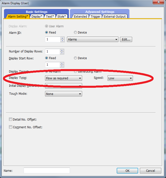
scrolling alarm displays can be done via the attached setting. i dont know if any way to scroll normal text unless you get fancy. probably just as easy to set up multiple alarm sets and use them to scroll whatever text you need.
-
are you talking about a splitter or a switch? you would need a switch, you can read from 2 or more plcs at the same time that way.
-
what is connected to the PLC? could be an HMI or SCADA system setting this. the latch relay could also be set via a batch command, so isnt as easy to find.
what software are you using to monitor the cpu?
-
D534 is a user setting in the engineering parameters. once set, in theory, it never changes.
if i was to delete it, if no one ever needs to change the value, there would never be an issue. but i get your point, i dont nromally delete code, unless its been tested as not needed, or i know what its doing.
i will have another look when i next get a chance. thanks
-
perhaps, but i cant see how a single increment would help?
im tempted to remove the calc to see what effect it has on the process.
it may just be one of those mysteries that will never be solved....
-
14 hours ago, Crossbow said:Why not use the USB cable? Why mess with Ethernet?
as above. set it up with the usb, then worry about setting up the ethernet connection afterwards when you have the cpu running with no errors.
-
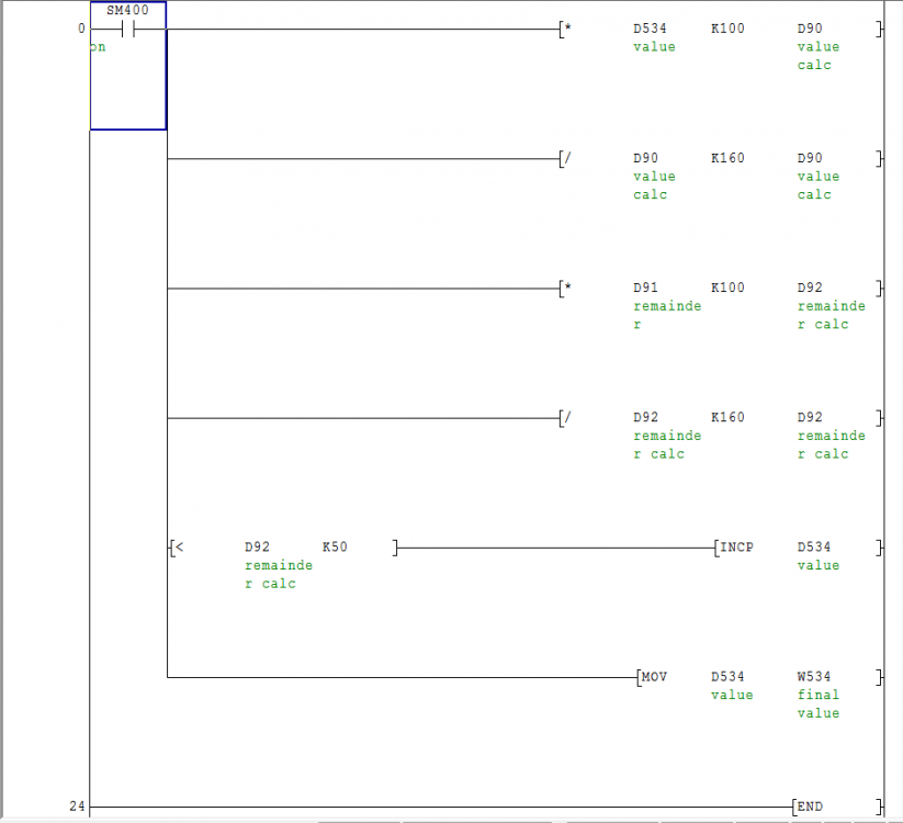
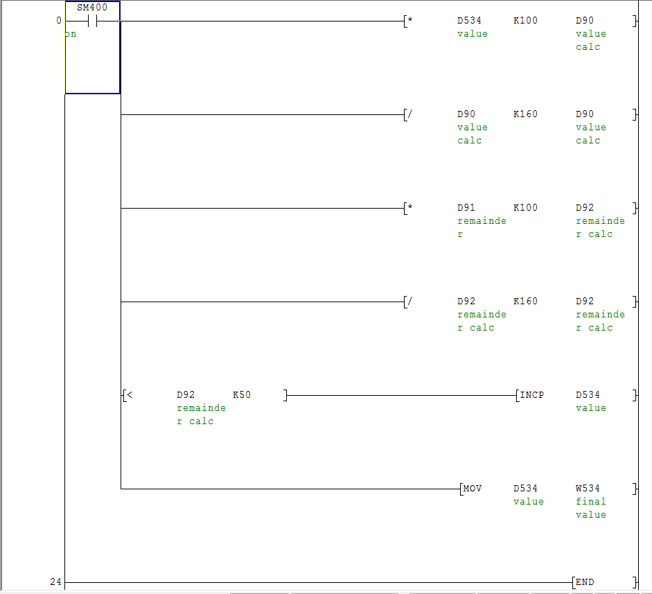
i can explain what it is used for, but i still cant get my head round it:
the value D534 is a setting value on our SCADA system for our malt kiln bed height shrinkage. this is a manually inputted value for how far the bed shrinks after the kiln cycle so the stripping arm knows how far to move down and begin stripping the grain from the kiln.the k160 value is the ratio we use to do all our calculations as the kiln is very old so everything is based on time with an upper and lower datum point only. this time is then converted to a mm measurement.
the stripping of the kilns is done in layers, 12 in total i think.in this bit of code; when you input a number in the SCADA, depending on whether the remainder calculation result is <50 or not, the value will either go in and stay, or be incremented by one?
i assumed i was just being stupid and it was a standard bit of a code for working out fractions of numbers and rounding up or down without converting the number to a float or something similar? i just cant see how it would achieve anything worthwhile?
thanks
-
please see attached screenshot of code.
can someone please explain it to me? my maths isn't the greatest anyway, i just cant get my head round what it is trying to achieve?
i can see that the calculations are being done, then the remainder overflows to the next register, the calculation is being done again and the result is compared against 50 which can increment the initial value.
there was some scale limits and other bits i have removed, it was just this section i didnt understand. please help!
-
On 11/20/2016 at 9:09 AM, Rodney said:As Kaare_t said you must remove the power and the battery to reset the PLC. If you try to download your program without a reset the PLC will request the password.
Rodney
i have found when using keyword passwords that you can still overwrite the program completely without having to put the password in?

ethernet comms between different networks?
in Mitsubishi
Posted
i wish, i am in a maintenance department. we barely have enough to keep things going, let alone spares to set up a test rig.
everything i do has to be on the live system!!!
i have no station number issues when i put them all on the same network, so wouldnt have thought it would be that? did get a chance to get on it last friday as had issues with something else :(
will try again this friday!