

tingxing
MrPLC Member-
Content count
61 -
Joined
-
Last visited
Posts posted by tingxing
-
-
Basically it does not matter if doing send/receive multiple times or once in a single command.
But, I found at my computer, reading a DM takes about 50ms, with baudrate of 38400bps.
for 50ms, it should have been processing: 50/1000*38400= 1920bits ~192bytes ~ 40words
So, it is reasonable to expect to be able to access much more DMs (or other words).
So I am trying hard to be able to send them in a single send/receive to speed up performance.
Hope this helpful for others and welcome much more advice too.
Ting
-
10 hours ago, photovoltaic said:FINS protocol doesn't support any sort of read from specific, spaced out registers in a single message. Now that I think about it I'm not aware of any protocol that does. Like IO_Rack said your best bet is to group them programmatically. This is common practice to cut down network traffic and speed up HMI polling
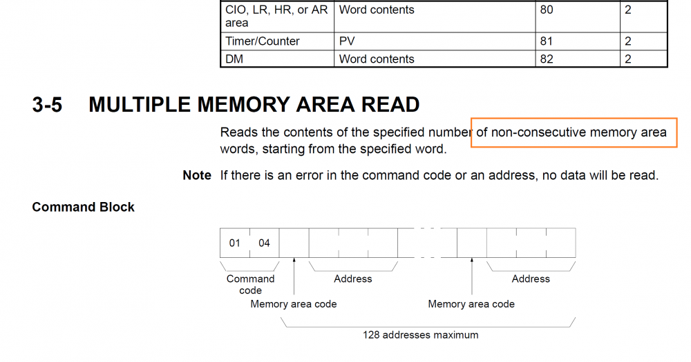
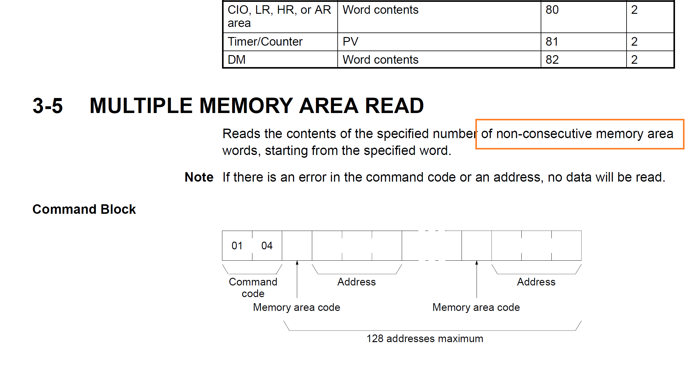
I read in a manual (W227E12_FINS_Commands_Reference_Manual.pdf) that there seems to be a command capable of doing such task.
Trying to use such kind of command is based on expectation of performance improvement:
for example, communication time of three times of reading: DM200, CIO3600, CIO 4000
50ms + 50ms + 50ms -> 150 ms
but reading once, might be only: 100ms
-> this is not expectation, but I guess there is really such performance merit, and would like to measure if possible.
Ting
 1 person likes this
 -
12 hours ago, IO_Rack said:Can you change the PLC program?
I would move the data into consecutive locations.
I purposefully avoid changing PLC.
-> we use personal computer to communicate with PLC to sample some of the DM, CIO etc device's status.
Changing PLC is a good way to do it efficiently, but this incurs extra work and possibility of mistake. and further more, you need to be on the site to do the change, while updating a PC's program need not.
-
18 hours ago, photovoltaic said:The protocol doesn't allow for this type of situation no.
Thank you for your suggestion.
After reading parts of the manual, I also began to realize this.
Probably, FINS command should be used (?).
Ting
-
Hello,
I am using Hostlink protocol to read data from PLC units.
for example @00RD22220001..., will return DM2222's value.
But I want to know, if I could read multiple DM values at the same time.
for example: DM2222, DM3000, DM4000, reading these DMs with one communication.
Please note that these are not continuous DM areas. I know a sequence of DMs can be read by specifying starting address and count.
Many thanks in advance.
Ting
-
cause of the problem might has been clarified:
too much current is found to be flowing through the safety relay - a calculation mistake, we should have chosen a relay type of higher specification.
To clear the problem, we changed the relay to a contactor.
Many thanks for the helpful suggestion.
Ting
-
Hello,
I want to know, if it is worthwhile to transfer from Q series to iQ-R?
Currently our equipment is using Q series, which ss a vacuum coating equipment with about 10 power instruments, 20 gas controllers, and pumps and so on.
As for the analog and X, Y points, Q is quite capable.
I can not see any advantage to switch to iQ-R, but some people want to.
So I want to know,
1. will Q be outdated in the near future?
2. will use iQ-R cost much more than Q? including peripheral units.
3. has iQ-R really been widely adopted?
4. thoug iQ-R may be powerful, I think use multiple middle size CPU's can be more advantageous,
is this right?
Many thanks in advance.
Ting
-
The safety relay is supplying 24V power line for CC-Link modules, and Emergency Stop circuit.
-
Thank you very much for the advice.
This relay is being used together with Omron's safety PLC, G9SP.
I am also wondering, if my logic is something wrong.
This symptom happened after the circuit had been being used for quite several weeks.
Then suddenly...
I try to extract the circuit for a clear check purpose.
Ting
-
Hello,
I am using Omron’s safety G7SA to relay 24 volt line.
But the strange thing happening is that, one relay’s output is only 5 voltage,
even the relay is on. I exchanged relays, it remains the same. Maybe the base socket is problematic?
Or is this just G7SA failure? 5v (exactly 4.96v) is strange.
Please give me some advice.
Many thanks in advance.
Ting
-
Thank you very much for your reference link.
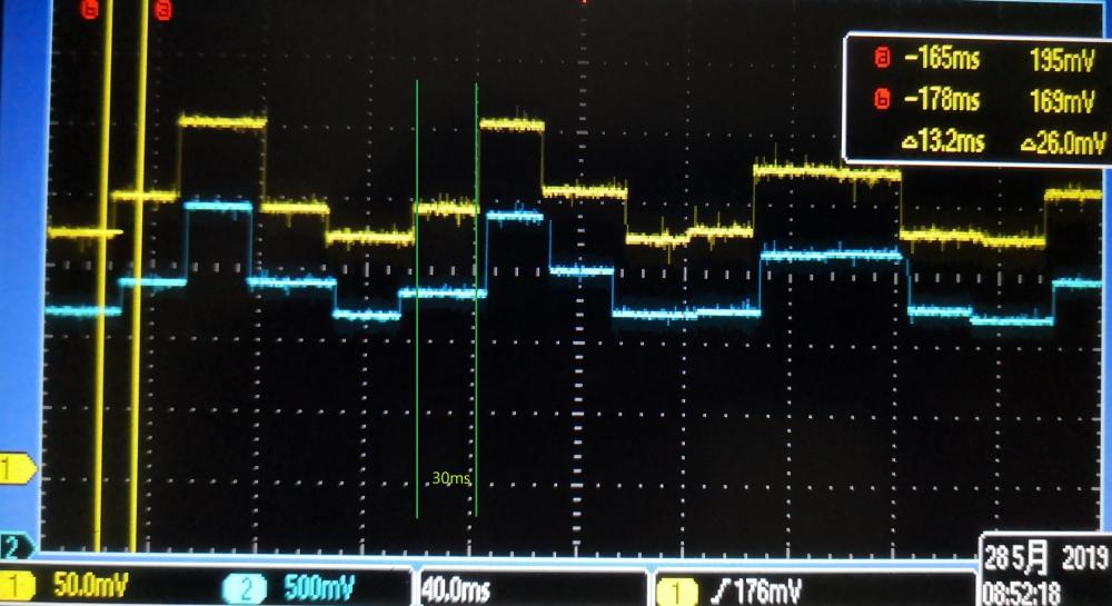
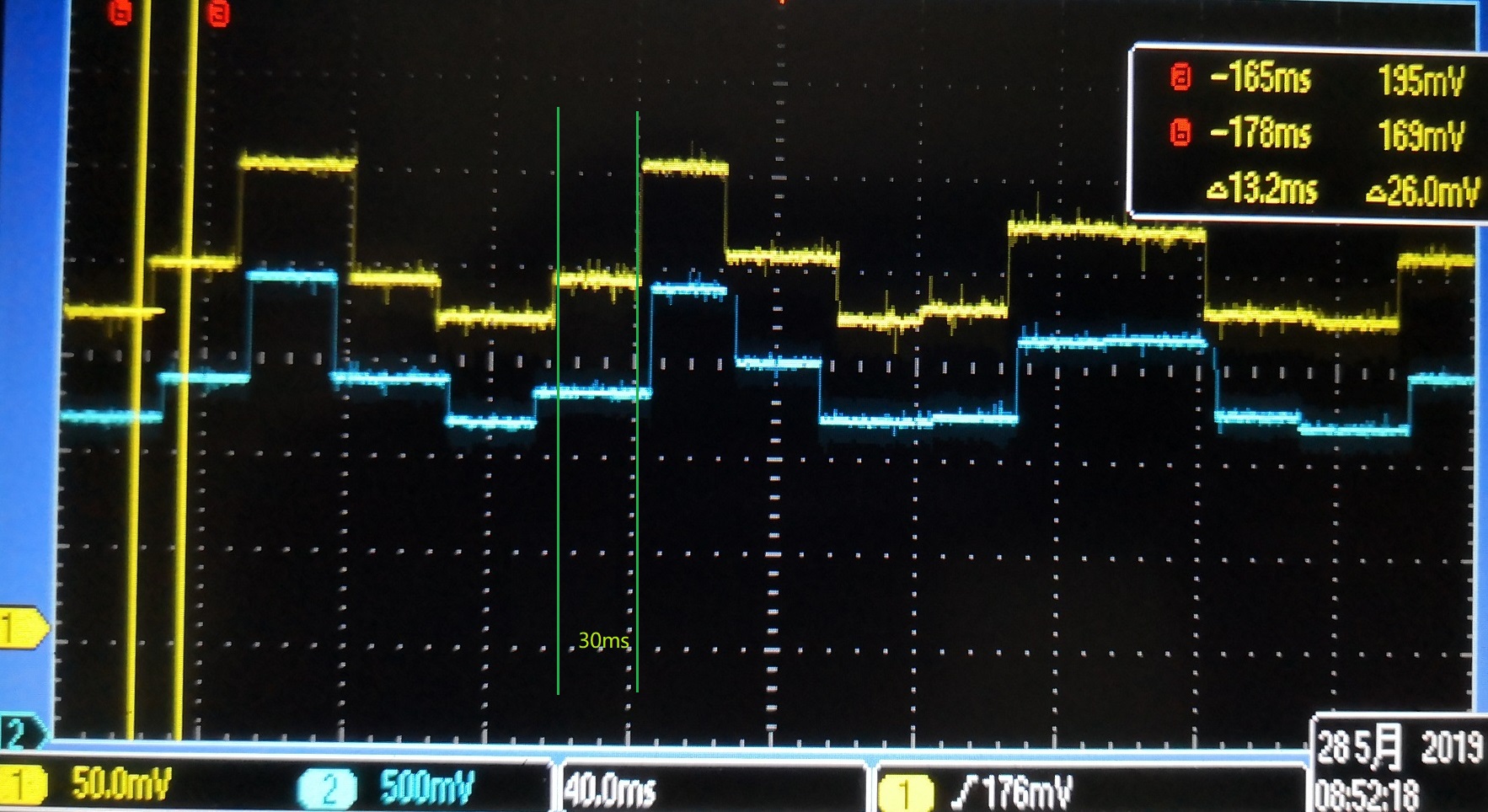
I am not sure, but what I got is not so quick: 10 points per 30ms.
what I got seemed to be limited to an interval of 30ms. The attached file is what I took from oscilloscope, which I output interpolated value from table by using SCL instruction.
Though the table has about 10 points to describe Sin curve, it should not have been so coarse as what is shown in the picture. The picture apparently shows the limit of 30ms.
I have checked scan time, which is 2-3 ms, and D/A's specification is 1ms/channel,
so the limit might be bottle-necked at somewhere else ...
Ting Xing
-
Hello,
I am trying to generate a wave form, such as sin, using mitsubishi's LCPU.
The problem I met is that time precision of the wave form generated is only about 30ms.
I checked my cpu scan time is about 2-3ms. my DA conversion specification is 1ms/channel.
I am afraid CC-Link communication delay is the cause, but not sure.
From the wave form, it seems some where time division is limited to about 30ms. I have expected at least for example 10ms can be obtained,
i.e. if the period of my wave form is 100ms, I can output and get at least 10 data points.
Would anyone give me some advice.
Many thanks in advance.
Ting Xing
-
Really easy? That will be quite assuring. Thank you for the manual and comparision of A and Q series. In Omron world, we ever used Loop Controller, which might be over-engineering, I think. Ting -
Hello, I have ever implemented PID control in Omron's PLC using its PID instructions. (thanks to the help of Mr. PLC's posts) Now I want to know if it is equally functional under Mitsubishi's PLC cpu's? Is the code complicated? Because I might only need one or two PID control loops, the processing overhead for CPU is negligible, is it right? Many thanks in advance. Ting -
Hello, I am not sure if this topic is too far from what the forum concerns, but any advice is greatly appreciated including reference to other reference. I want to know if any induction motor has internal encoder equipped. We are using servo motors, and additionally an encoder for position check. Because the position control resolution requirement is about 1 degree, I am thinking about abandoning servo motor, and to use induction instead. Servo motor has internal encoders for outputting pulse information. And I wonder, if there are induction motors with internal encoders. Thanks in advance. Ting -
Hi, Michael, Thank you very much. I got your idea. you mean adding offset to IR0? and I understand what to do: MOVR D0 IR0 -> yes, we use D device, and we just assign its initial address of D0 ; MOV D100 DR0 -> D100 has our memory block's starting address, we maintain it as a member of a table for all the memory blocks +L D100 IR0 IR0 MOV #1, +0,IR0 MOV #2, +1,IR0 MOV #3, +3,IR0 this is just what I wanted. before I posted here for help, in fact I had tested these codes, but not successful, because I mistakenly used +D100 IR0 IR0, in fact the instruction of +L should have been used. This is due to my ignorance of IR registers. Thank you Michael, and you all, for the enlightening instructions. Xing -
Hello, Michael, your solution surely addresses the problem, but it lacks a point I need very much: specifying address shift(offset) by using +1, +2, +3 ... I know that using DR0,IR0 and shifting DR0 one by one could iterate the memory block, just like MOV #1, DR0,IR0 -> assign #1 to ex. D2000 ++DR0 MOV #2, DR0, IR0 -> assign #2 to ex. D2001 ++DR0 MOV +3, DR0,IR0 -> assign #3 to ex. D2002 but this kind of writing is not good for maintenance, because it is hard to check the actual address offset just by reading the code, and the offset is in fact calculated at runtime. the following is expected: MOV #1 +0,IR0 MOV #2 +1,IR0 MOV #3 +2,IR0 this way, the address shift is clear, and definite by checking the code. any mistakenly deleted or added any line can be identified without difficulty, on the contrary, the previous method is hard and time consuming when any problem occurs. to use +0,IR0 poses no difficulty, if I just assign the starting address to IR0, MOVR D2000 IR0 but, to go back to my initial question, the problem is how to avoid using D2000 directly, but indirectly, for example, MOVR D0 IR0 -> yes, we use D device, and we just assign its initial address of D0 MOV D100 DR0 -> D100 has our memory block's starting address, we maintain it as a member of a table for all the memory blocks MOV #??? DR0,IR0 -> OK, we address the first unit of the memory block MOV #??? +1,DR0,IR0 -> this is what I want: offset the DR0,IR0 from here by using +1, +2, +3..... instead of ++DR0: because later I will forget where I am if the memory has tens or hundreds of items, which is normal, for example, in the case of control recipe application. MOV #??? +2,DR0,IR0 MOV #??? +3,DR0,IR0 ... MOV #??? +1024,DR0,IR0 Xing -
Maybe I could make it clearer in this way. We define several blocks of memory, and specify the starting addresses in a table: MOV #100, D0 -> block 1, starting from D100 MOV #200, D1 -> block 2, starting from D200 MOV #500, D2 -> block 3, starting from D500 and there are related instructions to assign values to these memory blocks, which might use MOVR instructions and IR registers. But if there is time to make any change to the starting address, I expect to limit the modification ONLY to the table itself. for example: MOV #1000, D0 MOV #2000, D1 MOV #5000, D2 Xing -
Thank you for the detailed advices (sorry for the delay) What I want to do is, to assign a sequence of values to a memory block. for example: MOV #1, +1,IR0 MOV #9, +2,IR0 the +1, +2 indicate the offset from IR0, and putting instructions in this way is of great readability. if the lines extends to +10, +11 ....., and every offset position has its own meaning. The problem is, IR0, i.e. the starting address will subject to change, for example, currently the following is just fine: MOVR D100, IR0 but later or in any other cases, I need MOVR D200, IR0 I do not want to modify the MOVR instruction, instead, I want to specify D100 or D200 (or their offsets') in a memory, for example MOV #100, D0 or MOV #200, D0 and if D0 is changed, the starting address will be changed. Since DR0,IR0 indicates an address, if the MOVR instruction could assign the address to IR register the problem would be solved: MOVR DR0,IR0 IR1 <- psudo code Xing -
Hello, Can I add an offset value to IR register? for example, MOVR D0, IR0 and I have an offset value stored in D1, for example, &100, could I add the offset of D1 into IR0, to get IR0 pointing to D100? I know I can just do MOVR D100, IR0, but for purpose of versatility, I want an offset to be added in such a way. Thanks in advance. Xing -
thank you Michael, now I understand CJ2 can do. and as you pointed out, CS1G wont work. And I tested BITS N BYTES' sample, it works! except that I changed the output to the SET instruction: the 128bit, after W0.0, i.e. W8.0 can be turned. thank you all for the instructions. as I stated above, the purpose is to translate a number (used as command code from PC) in to a bit command. In mitsubishi, the SET command conveniently translates the number into the B devices. I have long formed the bias that Omron's development tool(Cxprogrammer) is better than that of Mitsubishi(gxworks). This might be an exception? or I am actually wrong. Xing -
great! surely, it will be the Set command using Dxx offset. thank you for your example ladder! 1. really the No. 128bit will be set ? my current instruction manual (w474-e1-09_cs_cj_nsj.pdf, old?) says the offset should be constant 0-15 or word address in I/O memory. 2. is this command usable in CS1G? in my cxprogrammer, there is error report. though our production equipment uses CJ2M, I am currently using CS1G for testing. -
Thank you all very much! Yes, I am using the current CJ2M cpu's. for SETB W0 D0 if D0 = 128, will W8.0 be set? I mean, will the set operation span out to more than the one word(16bit) ? Xing -
Hello, I am looking for Omron PLC's bit set instruction, which is similar to Mitsubishi's, like, in Mitsubishi PLC: Set B1000Z0 if Z0 is 10AA, then B10AA will be set. has Omron's instruction set contains such functionality? In my application, PLC will receive a number for example N(i.e. a sequence number), and I want to set the set the Nth bit in a memory block (W or so). Many thanks in advance. Xing
TCP communication record
in Mitsubishi
Posted
Hello,
My PLC is connected to PC using ethernet port,
and the PC is requesting data (DMs) from PLC to do data logging.
I want to know if it is possible to check the latest TCP communication request's time stamp.
As a kind of something like handshake, so I can be sure the PC is still working.
Does Mitsubishi's PLC keep this kind of data anywhere?
Thanks in advance.
Ting