

lamboom
MrPLC Member-
Content count
185 -
Joined
-
Last visited
Posts posted by lamboom
-
-
20 hours ago, pcmccartney1 said:I was talking about LinMot and their claims to support multiple communications protocols including E/IP. Generally, those vendors will have manuals and example code to get you started, then you figure out the rest through trial and error.
On the Omron NJ side, I know that they have multiple add-on modules for various protocols including E/IP. Was wondering if they might have a manual concerning LimMot via any protocol.
At this point I'm assuming that you are planning to use an Omron NJ and need to talk to a LinMot servo drive. At this point, you plan to do so through EtherNet/IP. Certainly Omron is not my strong suit, I usually call my Omron distributor and he beats on Omron (Japan) until they give him a response.
Hi again.. Yes LinMot manuals can be quite vague in the instructions and "example" category .. But, they are getting better.. the walkthru manual they sent, and I just posted, is a good example of that. They finally started a suite of YouTube tutorials about a year ago.. and hopefully will add more.
As for the best reasons for using LinMot ... for me, that was a no-brainer. The LinMot Linear motors last forever, Billions an' Billions of cycles, they are "very" powerful, have only one moving part, can get splashed with water, are "very" fast (like a rail gun) or extremely slow... and are space efficient ... and, if required, are very-very accurate ... they are also a bit expensive
")
-
Latest News: LinMot support just sent a preliminary walk-through file on E/IP streaming to LinMot E/IP drive using a Rockwell CPU:
Microsoft Word - Rockwell_PVA Streaming_Walkthrough_Pictures.docx.pdf
Here it is in .docx:
Rockwell_PVA Streaming_Walkthrough_Pictures.docx
Now to find someone that knows Rockwell and Omron NJ...
-
LinMot support just sent a preliminary walk-through file on E/IP streaming to LinMot E/IP drive using a Rockwell CPU:
Microsoft Word - Rockwell_PVA Streaming_Walkthrough_Pictures.docx.pdf
Here it is in .docx:
Rockwell_PVA Streaming_Walkthrough_Pictures.docx
Now to find someone that knows Rockwell and Omron NJ...
-
Had to read your post ... thanks... will get back.. meantime check out
http://forums.mrplc.com/index.php?/topic/32436-nj-streaming-position-data-to-lin
-
NEWS FLASH ... I just got an email from Linmot about the programming of an Allen Bradley PLC for streaming to the E/IP Drive... Standby
I'll get right back to you haven't even read comment above... back soon...
-
No..... Many of my eMails have gone unanswered... However there are several very helpful people on this form that know quite a bit about the Omron NJ .. wonderful people..
Just thought of something... Were you talking about LinMot or Omron on the manuals and code statement you just made?
-
Been there..done that ...
This is the message I got from LinMot: " PVA streaming has been done with the Rockwell PLC, but the Ethernet IP bus needs to be updated at regular intervals (the requested packet interval between the PLC and the drive), and the task/ladder that has the streaming command is also examined at those regular intervals. " That's why I'm looking for a Allen Bradley expert.. who might know the specifics of what LinMot has said. LinMot is aware of my project using the Omron NJ to control the C1250-IP .. They don't give it high hopes .. In fact, they aren't approving my use of their E/IP drive on the NJ's E/IP port for position streaming. I can understand that. Also, LinMot is not very familiar with the NJ CPU... and, can't really help beyond the information above.
If it has been done successfully by Allen Bradley ... there's a chance there might be a way for Omron's NJ to do so too. LinMot doesn't know the "specifics" of the Allen Bradley E/IP streaming system. They just know what you see above. Hopefully there's an Allen Bradley expert out there that can comment with some clues and information. Regards, Michael
-
pcmccartney - Thanks for the info. I assume you are talking about a Rockwell system.. If so... I would need very specific details as to how that program might be written.
I don't know anything about Rockwell/Allen Bradley PLC's .. I'm trying to understand the Rockwell process, to see if it might be adaptable to a Omron. It's more about the philosophy which includes technical specifics. Once understood, I could try and see if Omron has a similar functionality.
Specifically... Is it possible to describe the steps, in order... and discus what they each do, using Alan Bradley .. kinda like a tutorial? Thanks, Michael
-
Speaking of the Nature of Ethernet/IP ... which tends to fail at this method of data streaming with LinMot. I asked LinMot support if has it ever been done by Rockwell (Allen Bradley) .. The answer was: "PVA streaming has been done with the Rockwell PLC, but the Ethernet IP bus needs to be updated at regular intervals (the requested packet interval between the PLC and the drive), and the task/ladder that has the streaming command is also examined at those regular intervals."
That sounds like a timed messaging system .. similar to Omron's CIP messaging (above)? Does the NJ have a '"Scan Timer" .. should I be using a TON to regulate commands to the LinMot drive at precise intervals?
Even then .. would Ethernet/IP get the message to the LinMot in a precise time sequence.... ?
Anyone know how Rockwell does it?
-
Using Ethernet/IP to stream position data to a LinMot Drive, may be quite difficult because the LinMot requires a precise period between data points. I've been told PVA streaming has been done with the Rockwell PLC, but the Ethernet IP bus needs to be updated at regular intervals (the requested packet interval between the PLC and the drive), and the task/ladder that has the streaming command is also examined at those regular intervals.
This sounds like a timed messaging system over Ethernet, to satisfy the LinMot's requirement for precisely intervaled packets, which would compensate for Ethernet/IP's general lack of precise timing between data packets. (the preferred method is to use EtherCAT)
Has anyone ever tried this.. ? Please describe the method with a little detail .. I'm trying to see if an Omron NJ can stream PV or even just P ... using their Ethernet/IP port. If Rockwell has done it successfully, I would love to know how... Thanks much... Regards, Michael
-
Inno --always nice to hear from you ... I appreciate you are very busy... there isn't any rush on this.. it's more about the journey than the destination. commenting on your reply's:
1) you are correct... I should have pressed Send Command... But it was greyed out. eventually solved that problem with trial an' error ...and .. yup..I did check Enable Manual Override too.
The good news is.. a fault was created in the drive when I hit Send Command ... I mentioned earlier(edit): Streaming requires at least two command events, (example: 2 ms apart) in order for the LinMot to establish the "period", or "Time Stamp". The position will be sent to the motor 1.5 periods later from Time 0, or at 3ms .. LinMot will expect another position at 4ms, and will send the 2nd position to the drive at 5ms from Time 0. The last command would be "Stop Streaming" It doesn't look like there is any way to simulate this streaming series from that TALK 6 Manual window.. which generally only deals with calling for a single position, at a single velocity, or acc... or a curve from a curve library.. etc. Makes one wonder why it's even there?
2) Ethernet/IP may indeed, not be able to do this. methinks too many other data packets are flying all over the network, presumably modifying the "Time Stamp"
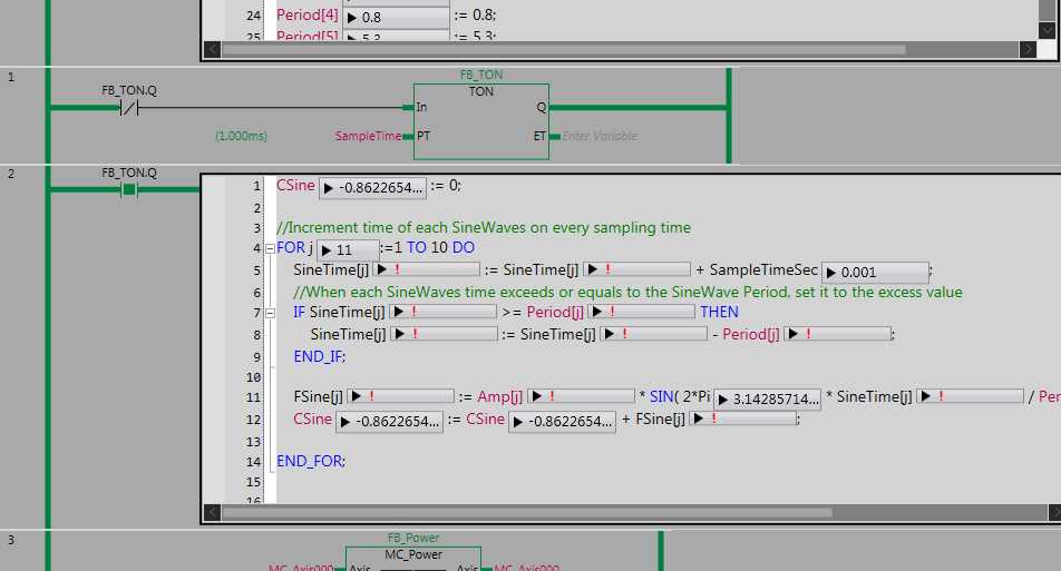
3) I'm not having any problem sending commands to the LinMot using other command modes, like VAI Go To Position (you can see that in the little video of my test rig) While I can get the "expected" Fault using TALK 6 and the Manual command mode window for PV streaming, by sending a single command.. and no other, thus overloading the buffer, I do not get a LinMot Fault when operating the NJ's program with this ST:

even tho, I do see the calculated data online:

Just nothing happens...not even a LinMot Fault .. you would think I would get that when the streaming fails ... soooo something else is not right.
I might be goofing something up.. like "Count Nibbles" ... whatever that is... sigh. Time to go back to the LinMot manuals...
4) Because there was great success in sending simple command mode settings to the drive, (I had access to a program that did that using an NJ) I assumed I could write something that would send "timed" commands, via Ethernet/IP ... and... that may still be possible... except, the LinMot claims the drive must receive "precisely" timed periods of commands... and that... may not be possible, because of the nature of Ethernet/IP?
-
Thanks to much help from the Forum, I have a G5 servo motor wiggling back an' forth randomly in rotary mode.
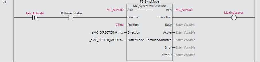
The position signal for that motion, is coming from the MC-SyncMoveAbsolute function block. (MC_Axis000)
Is there a way to convert that signal to Analog , ideally +&- 10 VDC .. for analog output on I/O ?
Thanks, much, Regards... Michael Lambert
-
One of the possible ways it might be done came from outside the Forum. It is suggested that CIP Communications via Sysmac might provide a solution.
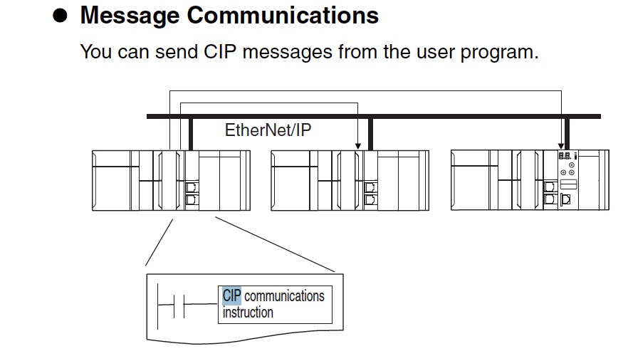
Intended by Omron to provide communication between Controllers using the E/IP port, Variables (position data for a LinMot drive) could be opened, written, sent..etc. via this method.
There is some indication that the "receiver" need not be a controller. Pages 2-1013 to 2-1068 of the 1800 page NJ Instructions Manual W502-E1-18 has a lot to say about CIP communication.
Unfortunately, It's not real clear to me how to use this for LinMot E/IP streaming. I wonder if this is the "Numerical Control", mentioned by LinMot?
-
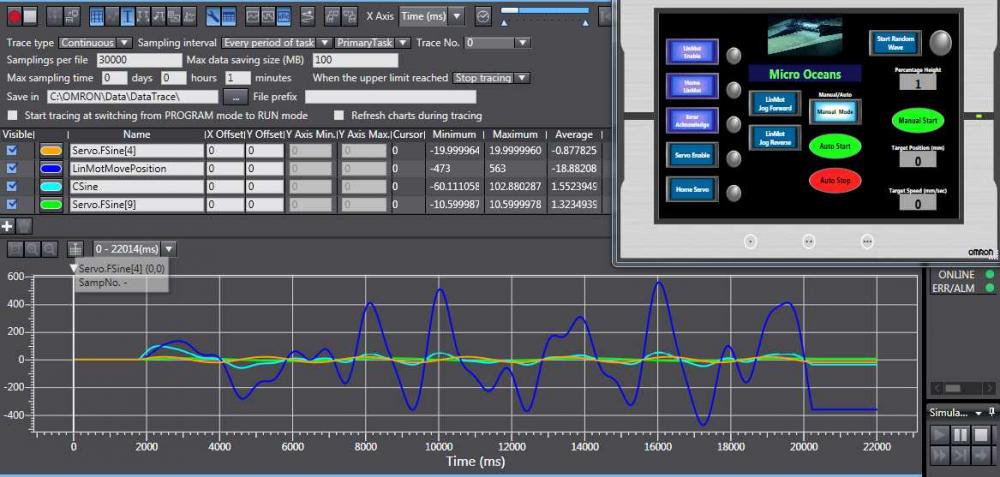
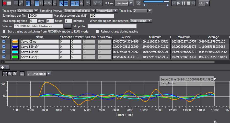
Now that the NJ is doing a great job streaming position data to a G5 Servo motor, Thanks to Tyler Corbett, Innoaloe, Michael Walsh, Crossbow, Berti & many others ..
(Blue trace)

The next trick is to get the NJ to run the LinMot Ethernet/IP Drive on the NJ's E/IP port. The NJ is already doing other things with the LinMot on that port... so it might be possible.
How hard could it be.. just....
In order to talk to the LinMot, you have to use Command Modes, and parameters like:
Kinda easy to call for a typical position move.
But, How about the Streaming position move... Here's what LinMot offers for options in that area:
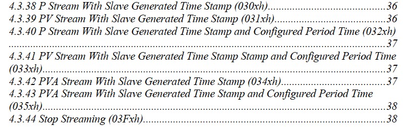
And here are the available definitions of those options:
...
...
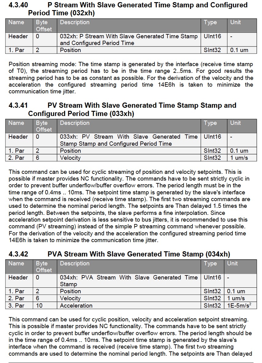
There might be enough info here to make an educated guess.. ‘cept I’m not well educated… sigh! (What’s NC Functionality, or Time Stamp or Configured Period Time?)
..methinks there are some limitations on the cycle period time .. could be as slow as 10ms .. but, that’s OK for making waves.
And that's about it..
Any Nj experts out there understand the above options .. enough to make a recommendation ?
Thanks much... Regards, Michael Lambert
PS: Below, recently discovered, is from a single page (84/106) in the LinMot Motion Control SW manual (2014) ( BTW: NC is "Numerical Control" .. do you know what that means?)
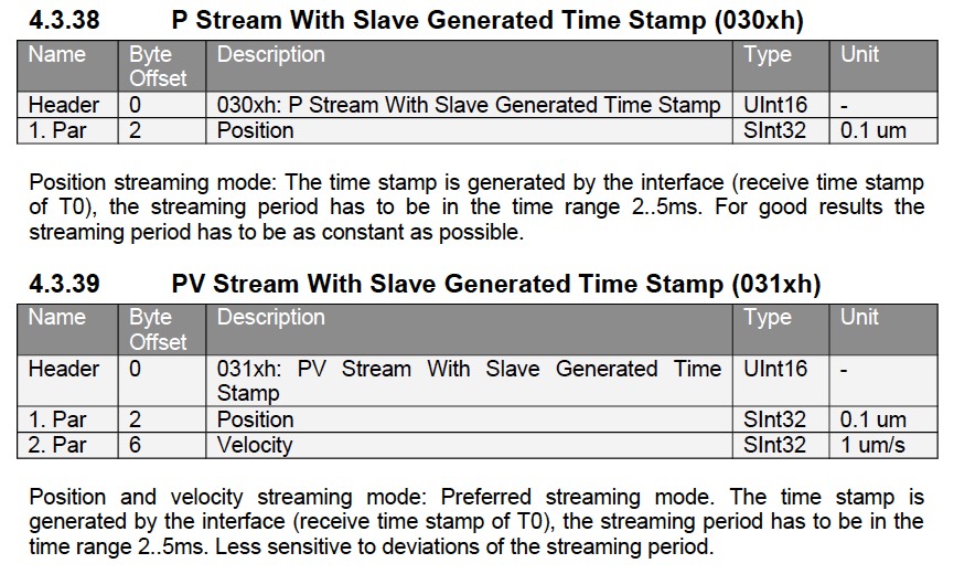
"P(V)-Stream
For masters with NC (Numerical Control) capabilities, the software supports cyclic streaming modes of the position and velocity, or position only. The streaming has to be strictly cyclic in the period range 2ms to 5ms. This feature is supported with all fieldbus variants like Profibus DP, CAN Open1, POWERLINK, EtherCAT, (No mention of Ethernet/IP .... sniff!)Different modes are supported:
In the first mode (Motion command: 030xh) the master only streams the position.
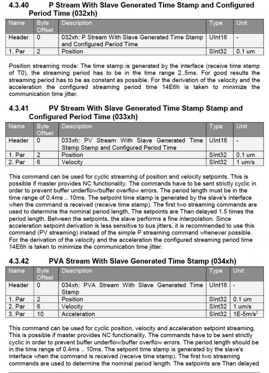
In the second mode (Motion command: 031xh) the master streams position and velocity, whenever possible use the PV-streaming mode, because the acceleration derivation is less sensitive to bus jitters than in the position only streaming mode.The third mode (Motion command: 032xh) is like the first mode, but for the derivation of the velocity and the acceleration a configured period time (UPID 14E6h) is taken, instead of the slave receive time stamp. This minimizes the bad influence of the transmission jitter.
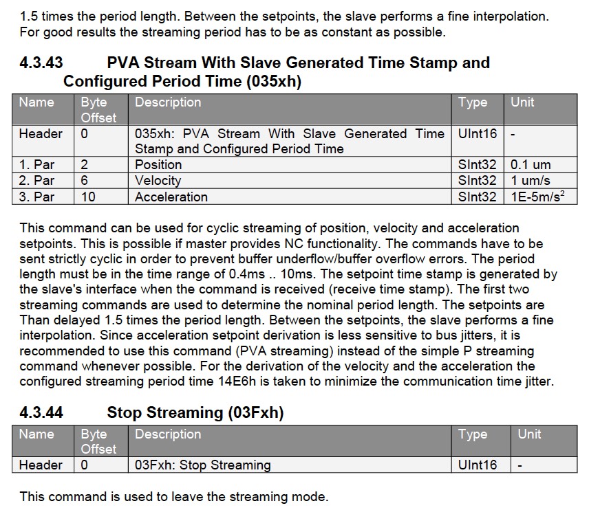
The position setpoint generation in these modes is delayed 1.5 times the streaming cycle time, e.g. with 2ms streaming period time the delay is 3ms.
In the P- streaming mode, it is possible that, depending on the cycle time, a quiet noisy motion is generated, this because of the twice derivation of the position signal to generate the acceleration value. In this case, it is recommended to set the position controller value “FF Acceleration” (UPID 0x13A0 and 0x13B4) to zero.
LinMot seems to recommend that the PV is the best mode for this use (4.3.39) ... :
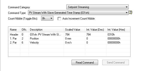
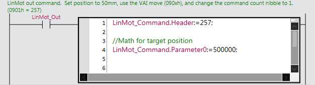
Possible Sysmac ST component:

the trick is to send the above every 2ms over Ethernet/IP
soooooo ..Does the NJ have "Numerical Control" ?
Can this be done with Ethernet/IP using the NJ ? ...or would it be easier using just P-streaming mode .. "position only"
I'm motivated to try with the E/IP ... because I only have an E/IP LinMot drive at the moment (can't afford the EtherCAT drive at $1200 yet)
Streaming requires at least two command events, (example: 2 ms apart) in order for the LinMot to establish the "period", or "Time Stamp". The position will be sent to the motor 1.5 periods later from Time 0, or at 3ms .. LinMot will expect another position at 4ms, and will send the 2nd position to the drive at 5ms from Time 0. ... etc. That's the theory.
-
Berti -Thanks for the reply. That picture was placed by mistake.. it showed the same thing that was at the top of this thread, plus the math for generating the sine summation in the large picture of the IF-THEN working to help "ramp" the start-up ... The math was created by innoaloe, on another thread.
-
Michael .. You're a wonderful person.
Thanks! (words .... sigh)
-
Michael ... Ya know, I really don't want to thank you with just words... On "Game of Thrones" John Snow's Wildling girlfriend always said "Words are wind" ...
There must be a way to show my appreciation ? Regards, Michael
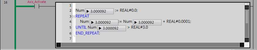
PS.. Wow.. I didn't know loops do it all in one scan .. that explains a lot!
-
Hi... This is kinda simple.. but.. methinks I may have a problem using the wrong Data Type with the REPEAT, UNTIL, END_REPEATE function:
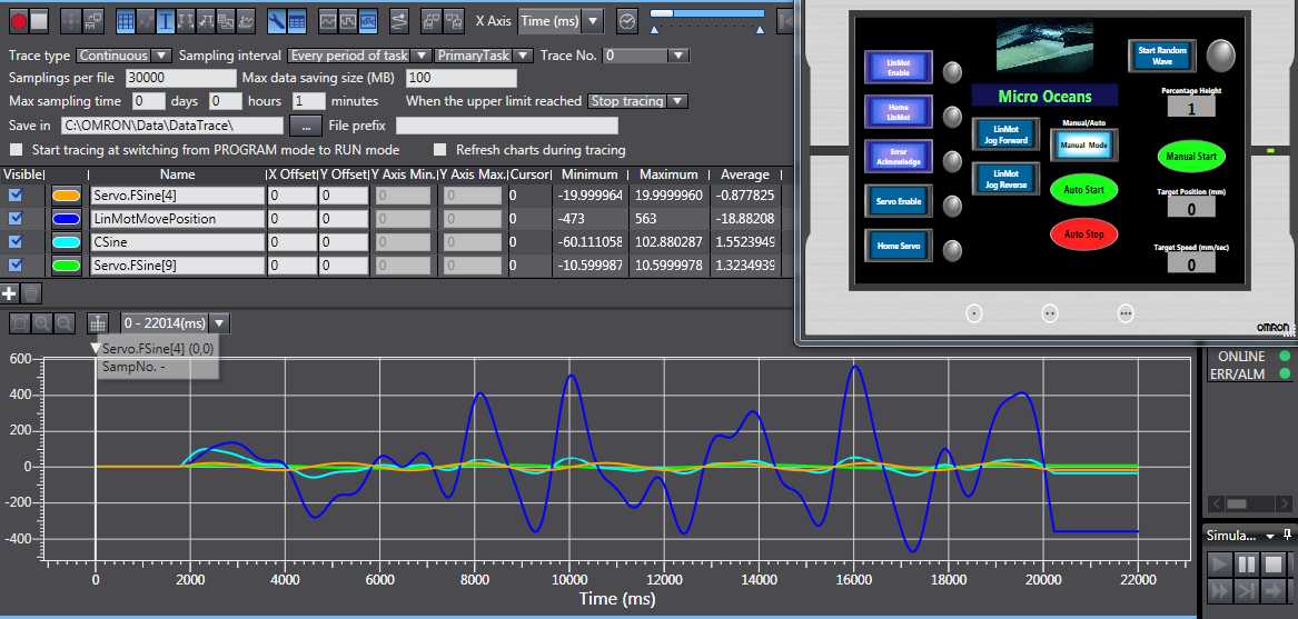
I'm trying to create a ramping function at the start of a position stream. The idea is to start the first point at zero and take 3 seconds to ramp up tp a preset "Percentage" of full amplitude of a changing position curve... Here's the curve in blue:
Normally, at first start of this curve, there is a rapid rise from zero ... which is too almost too fast.. I would like to bring the curve into operation, slowly... from zero .. Like a Volume Control ..
Here, I'm trying to use the REPEAT..UNTIL ...END_REPEAT ... The plan was to start at zero.. then, each CPU cycle add .0001 to "Num" ... and keep doing that until Num is greater than 3.
During this time, Num/3.0 is being used to multiply the position signal. I'm expecting Num to go from 0.0 to 3.0 in 3000 CPU cycles ..
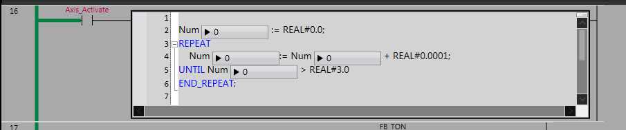
But... It doesn't .. instead it instantly (or, perhaps takes just a few CPU cycles) jumps to 3.0 :
Anyone out there know of a better way ro ramp a signal from zero to full in a set time?
Thanks much... Regards, Michael
-
G'Evening Inno ... Thanks for more good stuff... By the way.. I think it's working great! (I just have to study more, to understand why) It was probably working the first time.. but the buffer mode was probably wrong then .. sigh! This stuff is really difficult.. It works fine now with no errors..
The next challenge is the addition of slowly drifting phase angles ... very slow changes, so that no discontinuities occur .. might work in the RAND Function (page 2-218 of manual W502-E1-18 NJ Reference) Comments on your comments:
1) I took care of the warnings by making the variables Global ..
2) I added the input "Axis_Activate" to both the TON and the ST below it.
3) I think activation timing is OK, for now... because I always home before doing anything. However, a "real" programmer would make it impossible too screw up the proper sequence of events. I will follow your instructions. I'm also going to do much much more .. like alarm warnings, and adding alarm reset functions (I won't bug you about that.. I know how to do that part..
I Like the idea of reset CSine, all FSine, and all SineTime to zero, when homing. ..... will do.
Home position is as far as possible to the left of the tank. When wave sequences like Regular Waves trains, Rogue Waves, and Tsunamis run, they start from the far left position of the wave generator, and are defined with positive positioning from zero (initial position). The Random Sea must be made with positive and negative positioning. In order to avoid calculating a proper clearance "offset" move, so the generator doesn't hit the negative limit.. I just use an estimated "Offset" prior to wave start, When making the Random Sea, the generator cannot get too close to the back wall of the tank, or the water level behind the generator (wall) will rise above the tank. Some Wave making facilities continuously pump water from behind the moving wall, to avoid this problem.
After thinking about your "Offset" equation .. Methinks it will work to move the CSine up (or to the right) by a fixed distance, that would be good....
4) Thanks for the 'Watch Window" idea.. I have used it before .. and need practice ...
The reason I thought TON was "Kinda" Random.. is because it looks that way.. when "on-line" I see the green lines go on.. for a while, then off then On (like they should).. but they seemed not to be "regular"
By the way.. perhaps we should take this back to Messaging... now I'm sure no one in the Forum wants to read what we are talking about.
check this out: https://www.youtube.com/watch?v=BTCLrJuc01U
So much wonderfulness...
-
Gadzooks! you're up at midnight + it's 9:28 AM here.. ooops.. I just noticed you sent this 44 minutes ago... (I've edited my reply)
Observations: Program is working (sort of) .. and It's interesting what is happening.
1) There were only 2 warnings for your program, after I added the HMI:

I made them Global Variables, an that made Sysmac happy.
2) I've noticed the TON is active all the time, starting with P_On, and so CSine is always changing value, before one activates the axis:
3) activating the axis can be tricky.. with CSine not at zero.. a discontinuity can be large enough to cause an error when Axis is activated.. I added a "Axis_Activate" to the input line on both TON and the ST below it.. Works great now.. However, when random phase drift is added.. the output "CSINE" must be at zero, and slowly ramp to full Amplitude in about 3 seconds. That way starting discontinuities are never a problem. Also, there is the necessity to manage the final output amplitude, with a percentage modifier, slide or input on the HMI ... which will make quick changes to the average amplitude of the Sea, without adding any changes to the component's relative amplitudes. FYI: The amp/per component relationship is critical to the authenticity of the Sea state... nice to have an FFT component on the HMI too.
4) I'm curious why we don't see any information in any of the other boxes (notice the exclamation marks) Also, in the picture, the CSine on the left side of the final equation is equal to the CSine on the right.... I guess things are happening so fast, they don't register at all? It looks like CSine is changing by magic...
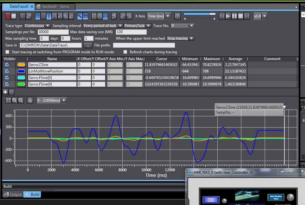
With the inputs as follows:
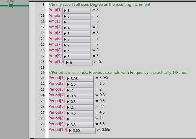
The motor is making a nice sine summation response ... Congratulations!
By the way.. watching the seemingly random way the TON is working .. and this program is working .. I still have very little understanding as to why it is working .. I must play with the Data Trace feature of Sysmac... I get the feeling that the NJ is either brilliant, or excessively complicated .. to be continued.
GADZOOKS! .... as i look at this thread.. it's enormous ... I'm thinking of removing much the problems. unless you like it as is... ?
-
Hello again inno - I'm so happy that you appreciate looking at this project. It's been a goal for me since mid 2010 ... I helped design this "tsunami" tank for the Museum of Science and Industry .. in Chicago, Illinois https://www.youtube.com/watch?v=crKNeA2pg-s
They only wanted a few different waves to inundate two shore designs. I was hired by the company tasked with building the tank, to do the engineering, and design of the wave maker, tank and shore designs. I built many models of the shores. At first the museum didn't want the water to splash the back of the tank, so the shore models were a little longer, and more complicated, with various land formations, and objects that would mitigate flooding, yet permit a very large wave to hit. When they saw how big the wave could be made (The largest wave took about 800 pounds of force to generate) They loved the big splash at the back. However, that's not a Tsunami.. it's just a "big wave" A tsunami is a very "long" wave with a period in the 10's of minutes. I managed to talk them in to having many normal "regular" waves, which could be made at the highest possible amplitude the laws of physics would allow... and yet none of these waves would inundate the shore models. The cliff model even had islands, a cave.. and a "blow hole" .. but, the museum thought that was too complicated for young minds trying to contemplate tsunamis... so the shore with a cliff became only 2 dimensional, and simple ... I also wanted them to show the "Random Sea" when no one was using the tank.. just to have the normal ocean ... that way, kids could see how waves travel at different speeds, and form up now an them as "Rogue waves" The tank is 33 feet long! ... plenty of time for that to happen... again.. too complicated... sigh!
Anyway... Once again, you significantly show the possibilities of Omron's NJ to do this job... There's no big money here .. in fact, there's probably none. I'm just trying to make a system that is affordable to schools, and museums. (the wave tank at MSI was enormously expensive!)
1) I tried other buffer modes,, but not that one.. I find the manuals somewhat overwhelming .. but, there's always some good stuff there if you keep reading them.. over an over..
2) I should have caught that too.. for now, one sine wave was enough.. if that worked, then on to 10 .. or more.
3) Yup...
4) Yup...
5) Sounds complicated.. but I appreciate where you are going with this.
6) I didn't try to run your original program.. I can't, because my CPU is a NJ101-1000, and using the G5 motor & drive (I'm already set for 8388608 where did ya get 1048576) ... I changed to 1048576. works OK.
7) I made Pi := LREAL#3.14159
what's with this 22/7 stuff?
I really like ST... I only shifted the FB out to look at it better .. Remember.. I'm the ultimate nubie .. you probably shouldn't be seen talking to me...
By the way... I am amazed by your "Data Tracer" above.. GADZOOKS! ... is that something in Sysmac?
Bye for now.. off to explore your work... Thanks again. Michael
PS: You will notice my MC axis is Ax0 .. that's from the program that Michael Walch gave me for homing the G5 incremental motor .. I was just adding your program to his for testing.
-
On 2/24/2017 at 10:29 AM, lamboom said:Let's say the actual cycle is only 0.5 ms, you'll still adding 1 ms to the sine wave time counter, which will cause the sine to progress faster than it actually is.
But..isn't the cycle time fixed at 1ms..? (or 2ms or 4ms)
Does Sysmac have sine function block, that would work with my linear equation: Amp * SIN( 2.0 * PI / Period * Time + Phase * PI/180.0) ... I'll see if I can find one.... (still, would like to make this one work ...)
-
Hi Jpratik92 .. I feel your pain.. I had the same /similar problem. Network Configurator is a nightmare for me.. Not only am I a newbie on the Forum, but also a real Nubie when it comes to Automation Engineering with networks.. so, I can't help you .. yet. However, if you do find help here, and I think you will, I will be watching
... for my own education.. Good Luck!
-
News Flash: innoaloe Replied to a message I sent him which summarized this thread .. well , it's not really a thread unless someone other than me comments on it..
From innoaloe :
Thanks for contacting. Sorry, I'm not really checking on the forum these days. Got some projects going on ATM.
Good thing that you've solved the homing issue.
Regarding some of your questions :
- I'm not really sure what went wrong with the FOR instruction in my previous example. Regardless, I attach here a new sample code (Sysmac Studio *.csm2 file). Just for simplicity, make the workaround with arrays for simpler code
- I didn't consider the MC_SyncMoveAbsolute function before. Indeed as Walsh mentioned it will be a better option. So velocity limit will be controlled directly from the axis setting, and no velocity input is required. I had given also example in the attached code.
- Regarding Frequency/Period, my previous example was using Angle as the input of the Sine function. In theory the Angle has relation to Frequency/Period as in Angle = 2.(PI).Freq.time or Angle = 2.(PI).time/Period. So in my original code, I didn't consider the current time. Basically it will continue to the next angle on each CPU cycle
- What I'm concerned about is the usage of Cycle Time as the "time" argument that you intended to use. There is this instruction to get the Task Period / Cycle Time of the CPU called GetMyTaskInterval, but the thing is it can randomly changed. We can put a maximum limit of Cycle Time, e.g. 1 ms, but should the execution takes shorter than 1 ms, the Task Period will change also.
- Let's say the cycle time is always 1 ms, putting that into the previous equation will result into a constant Angle. Because Freq/Period is also constant. That means the resulting wave amplitude will also stuck into the same value, to which no sine wave will be generated.
So my suggestion is to make a preset Timer, e.g. 1000 ms, then we use the timer current value of the timer as the "time" argument. The Timer will be auto-reset after reaching 1000 ms. I put this in the sample code also. Though, please modify the Axis Setting based on your application.
I might be misunderstood about point 4 and 5 though. Regardless you can review the sample should it suitable or not.
Oh, and you can call me Inno. Hope your project going down smoothly, Michael.I replied:
Hello inno ..
What a wonderful reply! ... I suspected you were very busy. It's a fine thing you do on the Forum. I may have said before that I'm not an automation engineer, or designer of motion control systems; however, I do know enough to get in trouble. I'm only working on "one" project .. don't expect to ever work on another ..
It's been a long process. Started with linear actuators that could make sine waves (S-curves) but not enough power, or velocity ..
Then, I discovered LinMot ... an awesome linear motor, Billions of cycles, 1 moving part, very powerful, very fast, accurate, and ... their servos, along with their communication software: "TALK", had built in curve design functionality, storage for 100 curves, I/O's for simple non-PLC control, and yet, would work easily with PLC's, and motion controllers in networks.
When Omron came out with the NJ, with a Motion Control module, two network ports .. I had to find out if it could make the Random Sea. I'm still not convinced that it can.
Thoughts about your welcomed comments and suggestions:
1) I messed up the FOR instruction because I used the wrong data type for "angle" (REAL) .. also I didn't see an "increment" part of your FOR instruction .. if angle was going to go from 1 to 360 ..how fast was that going to happen? so I added 1 .. which wasn't very smart, because it would only take 360 CPU cycles .. which would happen in only 360 ms! to complete one sine sequence.. and then would stop. I should have used an increment of .001 (will try it this morning just for fun if I can figure out the data type)
2) My frequencies (actually inputted as periods).. ocean waves have periods, never frequencies
fortunately, nothing should change fast enough to cause a position error/fault in one cycle time (1.0 ms)
3) I should go back to your original plan to see how that would work. It looked to me like all three waves would be the same period, just displaced in phase.
4) & 5) Yes.. We couldn't use task period cycle time (or task interval).. But, I understand the CPU cycle time is constant, and can be set for 1ms, 2ms or 4ms. which is fine. I was actually going to use WaveTime := Wavetime + Cycle time at the end of each loop, so the only thing that changes in my large summing equation is time by, 1ms.
By the way.. there has to be some amplitude control. I would put a "percentage" multiplier at the head of the summing equation that could modify the position result from 0 to 150%
Also, to prevent violent starting, splashing, and discontinuities at the beginning.. especially when phases are being used, a ramping function for the first 3 seconds of wave calculation would be necessary.. perhaps something like:
//Notes:
//Phx is in degrees
//WTime is in seconds
//CxPer is in seconds
//CxAmp is in inches
// M_Pi is Pi (3.34159)
//Percent (inputted as: 0 to 150)
//Height (0 to 1.5) equals Percent factor, multiplying the summing position result.
CycleTime:= INT#0.001? This data type is wrong.. but I can't remember at this moment what it should be.. DUH
Num := INT#0
WaveTime:= 0.0// Assume Percent is equal to 25 .. Height must grow from 0 to 1 in 3 seconds from start_wave. or 3000 cycles
// The following is a 3 second ramping time for the variable “Height", making it go from 0 to "Percent" in 3 seconds.
Num:= INT#0
REPEATNum := Num + INT #0.001 (must fix data type)
UNTIL Num > 3 // it will take (3000) 1ms cycles to reach 3 seconds
END_REPEAT;
Height := Percent * Num / 3.0;
WAmp := Height * ( C1Amp * SIN( 2.0 * M_PI / C1Per * WTime + Ph1 * M_PI/180.0) +
C2Amp * SIN( 2.0 * M_PI / C2Per * WTime + Ph2 * M_PI/180.0) +;
C3Amp * SIN( 2.0 * M_PI / C3Per * WTime + Ph3 * M_PI/180.0) +;
C4Amp * SIN( 2.0 * M_PI / C4Per * WTime + Ph4 * M_PI/180.0) +;
C5Amp * SIN( 2.0 * M_PI / C5Per * WTime + Ph5 * M_PI/180.0) +;
C6Amp * SIN( 2.0 * M_PI / C6Per * WTime + Ph6 * M_PI/180.0) +;
C7Amp * SIN( 2.0 * M_PI / C7Per * WTime + Ph7 * M_PI/180.0) +;
C8Amp * SIN( 2.0 * M_PI / C8Per * WTime + Ph8 * M_PI/180.0) +;
C9Amp * SIN( 2.0 * M_PI / C9Per * WTime + Ph9 * M_PI/180.0) + ;
C10Amp * SIN( 2.0 * M_PI / C10Per * WTime + Ph10 * M_PI/180.0));WTime:= WTime + CycleTime;
// the servo position calculation continues until stopped, with the WaveTime incrementing each cycle time of 0.001 seconds
Yes ... I think the NJ doesn't calculate sines this way... I will have to adapt... Hopefully, your example will help.
Thanks so much for an example code.... I'm going to owe ya big time
6) PS: We should keep this on the Forum.. for the members benefit. Although, I suspect position as a function of time is not often a factor in machine design.
He Then replied:
Hi Michael,
it's about midnight in my place now, so I'll look more into your algorithm later on :D
I still had a little doubt though about the idea to use 1 ms as increment value by depending only with the CPU cycle time. As I stated before, even though we set up CPU cycle time to 1 ms, it may goes faster than that if the whole program execution doesn't need that much time.
Let's say the actual cycle is only 0.5 ms, you'll still adding 1 ms to the sine wave time counter, which will cause the sine to progress faster than it actually is.
You can check the actual/minimum Cycle Time from the Task Settings. I attached an image to find where.So if you need to really kept the increment time to 1 ms, it's better to use the TON function that I provided before on the sample with Set Time to 1 ms.
Regarding *.csm2 file, it is a compact version of Sysmac Studio project file which only contain programs and hardware setups.The *.smc2 file will also contain Data Trace Logs (yes, Sysmac can do that, you can check whether your sine goes correctly by simulation first) and Event Logs. This usually takes 2 MB file size at minimum. On the contrary *.csm2 files would goes around hundreds of KB at most.
Since you're the topic owner, feel free to share this thoughts on the forum :DCheers, I'm gonna hit the sack atm


NJ Streaming position data to LinMot
in NJ Series / Sysmac Studio
Posted · Edited by lamboom
Yes, Inno ... Communication with the LinMot is working well with simple tag commands for position "go to" commands, Jog, Home etc.. all had to be satisfied via Sysmac and Network Configurator ("NC" is the most difficult and frustrating program I have ever encountered, by the way") I have not been able to send the "first" streaming command to the drive, as shown in the ST above in reply #3 .. which is quite disappointing .. I should be able to start the stream .. then see it fail ... with a Fault. on the drive... as it does when streaming is simulated using LinMot's TALK 6 software. In fact, it is impossible to simulate streaming from that software; but, as I said above, it is possible to START the stream, using the Command Header 784 ... A test position stream can be ramped from zero, and take a while to get somewhere.. so, there is no problem with too large a position increment .. which would cause following errors. The Error that pops up in the "simulated" stream using software.. is buffer overflow because there is only one point sent at the start.. and no 2nd point can be sent.
I have not been able to send the "first" streaming command to the drive, as shown in the ST above in reply #3 .. which is quite disappointing .. I should be able to start the stream .. then see it fail ... with a Fault. on the drive... as it does when streaming is simulated using LinMot's TALK 6 software. In fact, it is impossible to simulate streaming from that software; but, as I said above, it is possible to START the stream, using the Command Header 784 ... A test position stream can be ramped from zero, and take a while to get somewhere.. so, there is no problem with too large a position increment .. which would cause following errors. The Error that pops up in the "simulated" stream using software.. is buffer overflow because there is only one point sent at the start.. and no 2nd point can be sent.