

Inntele
MrPLC Member-
Content count
791 -
Joined
-
Last visited
Posts posted by Inntele
-
-
1. To the PLC it is necessary to transfer only three values: k, Xi-2, Xi-1. This should be done just ONCE , BEFORE the sine wave calculation.
2. To provide the requirement of item 1 you should not use a PLC input to activate the command sequence, a marker has to be used for this purpose.
How the item 1 and 2 can be realized in HMI:if ([b:X1= 1] & [b:M1= 0]){ set ([b:M1]) ; //if X1=1 & M1=0, then set M1 (SineWave Flag) [flt:GD400]= ... ; //dAngle= Pi*Freq*Tscan/-500 [flt:GD402]= ... ; //k= 2*cos(dAngle) [flt:GD404]= ... ; //Xi-2= Amp*sin(dAngle) [flt:GD406]= 0 ; //Xi-1= 0 bmov ([w:GD402],[w:D400],6)}; // transfer the precalculated values into the appropriate PLC registers if ([b:X1= 0]){ rst ([b:M1])} ; //if X1= 0 , then reset M1 (SineWave Flag)3. Check carefully the predefined values calculations in HMI. The k value must be positive, and the xi-2 value must be negative!
4. The code in PLC should look as is shown below, except of the code must be activated with a SineWave Flag (M1)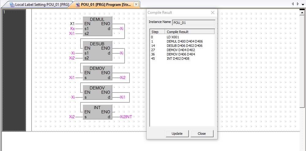
5. Decrease the value of sine wave frequency (52,4 is too high), increase the amplitude of sine wave, otherwise in the analog output you get a direct line, instead of desired sine wave.
1 person likes this -
I strongly recommend you to use the second algorithm of sine wave calculation, proposed by me.
In what are you wrong:
As I said already, in contrast to D8010 the D8039 is represented in 1ms value. Pls, take it into account!
Also you should remember, that if the scan time will be set as 10ms, at the mentioned 10Hz, you'll get 1/(10Hz*0,01s)=10 points only. At 1Hz you'll get 100points. With 4ms scan time at 10Hz you'll get 25 points, with 2ms scan time - 50 points of a sine wave amplitude, and with 1ms scan time - 100 points.
Having a GOT HMI, that able to calculate trigonometric function, you don't need to implement this calculation using a Taylor series...
Before to start the simulation of sine wave In PLC, calculate in HMI the differential angle:dAngle = Pi*D8039*Freq/-500, if the Freq is represented directly as REAL, or dAngle = Pi*FLT(D8039*Freq)/-5000 , if the Freq is represented as INT in 0,1Hz units.Because the D8039 is set by you, you just can use a constant instead of register value.
Then calculate in HMI:
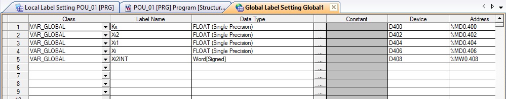
k = 2*COS(dAngle) Xi-2 = Amp*SIN(dAngle) Xi-1 = 0
and write these values into PLC,
The code in PLC is following:
LD SineWave DEMUL k Xi-1 Xi DESUB Xi Xi-2 Xi DEMOV Xi-1 Xi-2 DEMOV Xi Xi-1Then value of xi-2 can be converted into INT to sent it to the assigned channel of Analog Output Module.
That's all that you need to do.If questions will appear when the abovementioned steps are relized by you , pls don't hesitate to ask
") 1 person likes this
1 person likes this -
13 hours ago, plat933x said:Did I make too less polynomials in the formula for Taylor series(now it's y = x-x^3/3!+x^5/5!)?
Yes, for a quite high accuracy the polynom should has at least 4 elements, i.e. sin(x)= x - x^3/3! + x^5/5! - x^7/7! . Why? When x is in the range of -1<=x<=1, the maximum approximation error is 1/9! = 2,76*10^-6, i.e. is less than 0,0003%, while with 3 elements the maximum error is 1/7! = 0,02%.
Don't use the first algorithm of sine wave calculation, proposed by me! At 2*Pi angle the approximation by Taylor polynom using 5 elements will give a value (2*Pi)^9/9!=42 and the error about 350%.
-
Let 'begin from the end.
13 hours ago, plat933x said:I wondered about scan time of PLC, what do you think, is it possible to change scan time with M8039 and register D8039 to achieve changing of frequency of sine in much simplier way - regarding to attachment 3 and 4? For example when I use sine wave function with 1 Hz frequency and scan time D8039 = 100ms, changing value of D8039 from 100 ms to 200ms will change frequency on 0.5 Hz?
Yes, when I say about a constant scan time I mean the D8039. The value of D8010 is measured in 0.1ms units, while the D8039 is meaning in 1ms. Thus, if the value in D8039=100, the D8010 will be equal to 1000 and the scan time will take a 100ms.
However ...
The scan time of 100ms is a too much value for the FX3 PLC series. A typical scan time is from 4 to 10ms, and the abovementioned values is valid for programs with greatly complex algoritms. Also, if you are set a scan time as 100ms, for the 1Hz frequency of sine wave you'll just get 10 points of curve... (in case of 0,5Hz you'd just get 20 points).
-
Generally, how to calculate the instant amplitude of a sine wave in scanning.
At the first stage it is necessary to perform the initial calculation:
k = 2*COS(Tscan*Freq*Pi/-50000) Xi-1 = Amp*SIN(Phase) Xi-2 = Amp*SIN(Tscan*Freq*Pi/-50000 + Phase) where: Tscan - the PLC scan time (a constant scan) [0,1ms] Freq - the frequency of a sine wave [0,1Hz] Amp - the amplitude of a sine wave Phase - the phase shift of a sine wave
Then in each scan it is necessary to perform the operations:Xi = k * Xi-1 - Xi-2 Xi-2 = Xi-1 Xi-1 = Xi The instant amplitude of a sine wave at the current scan is stored in Xi-2.Example:
Amp = 10
Offset = Pi/3
Freq = 1,3Hz
Tscan = 4ms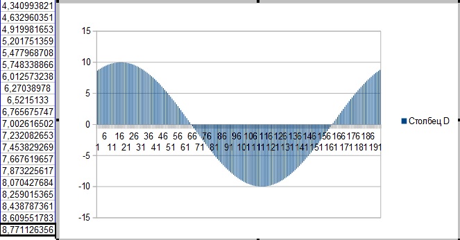
How to calculate the initial values in PLC, which does not support trigonometric operations, but supports a square root:
k = Tscan * Freq ;Calculation k = SIN(Tscan*Freq*Pi/-50000) by PLC implementation of Taylor series k = k * Pi k = k / -50000 k = SIN(k) Xi-1 = SIN(Phase) ;Calculation Xi-1 = SIN(Phase) by PLC implementation of Taylor series Xi-2 = Xi-1 * Xi-1 ;Calculation Xi-2 = COS(Phase) = SQRT(1-Xi-1*Xi-1) Xi-2 = 1 - Xi-2 Xi-2 = SQRT(Xi-2) Xi-2 = k * Xi-2 ;Calculation Xi-2 = SIN(Tscan*Freq*Pi/-50000)*COS(Phase) k = k * k ;Calculation k = COS(Tscan*Freq*Pi/-50000) = SQRT(1-k*k) k = 1 - k k = SQRT(k) Xi = k * Xi-1 ;Calculation Xi = COS(Tscan*Freq*Pi/-50000)*SIN(Phase) Xi-2 = Xi-2 + Xi ;Calculation Xi-2 = SIN(Tscan*Freq*Pi/-50000 + Phase) k = 2 * k ;Calculation k = 2*COS(Tscan*Freq*Pi/-50000) Xi-1 = Amp * Xi-1 ;Calculation Xi-1 = Amp*SIN(Phase) Xi-2 = Amp * Xi-2 ;Calculation Xi-2 = Amp*SIN(Tscan*Freq*Pi/-50000 + Phase)
How to implement a SIN calculation using a Taylor series is shown there .
-
No, have not a new, i've thoughly tested this algorithm and it works fine.
Just about the initial caculation of Xi-2 in PLC. With traditional Taylor series it's easier:
Xi-2 = Freq[0,1Hz] * Tscan[0,1ms] * Pi / -50000 b = Xi-2 a = b * b b = b * a / -6 Xi-2 = Xi-2 + b b = b * a / -20 Xi-2 = Xi-2 + b b = b * a / -42 Xi-2 = Xi-2 + b
But you can implement this initial calculation with HMI script.
-
P.P.P.S.
How to calculate the initial values in FX3G PLC directly:
Xi-2 = Freq[0,1Hz] * Tscan[0,1ms] * Pi / -50000 k = 2 * ESQR ( 1 - Xi-2 * Xi-2)The first equation is valid for infrasonic frequencies. In other case, a calculation should be implemented by Taylor series:
а = ( Freq[0,1Hz] * Tscan[0,1ms] - 25000 ) * Pi / 50000 Xi-2 = -1 a = a * a / -2 Xi-2 = Xi-2 - a b = a * a / 6 Xi-2 = Xi-2 - b b = a * b / 15 Xi-2 = Xi-2 - b b = a * b / 28 Xi-2 = Xi-2 - b b = a * b / 45 Xi-2 = Xi-2 - b
1 person likes this -
P.P.S.
In the Internet I found a very-very simple algorithm for a sequental calculations of a sine wave amplitude, which is easy to implement in PLC. Preliminary, to test I've modeled it using the Excel and the result for 1.3Hz at 4ms constant scan time is shown on the figure below: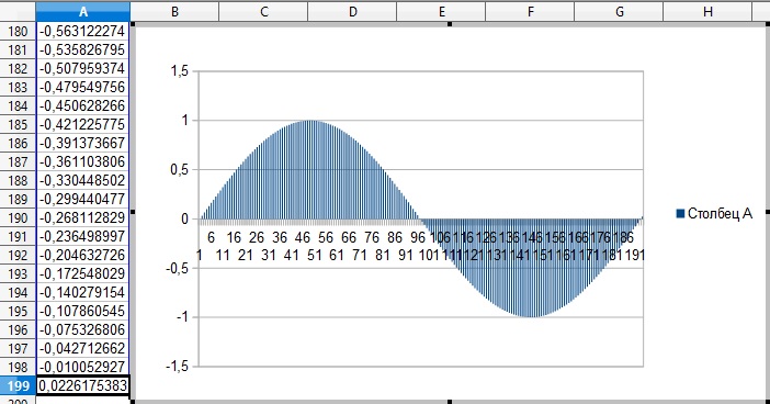
The algoritm requires only 8 registers (4 REAL).
Initially it is necessary to calculate two values: a coefficient and a starting value:
k= 2 * COS ( 2 * Pi * Freq [0,1Hz] * Tscan[0,1ms] / 100000 )and
Xi-2 = -1 * SIN ( 2 * Pi * Freq[0,1Hz] * Tscan[0,1ms] /100000 )Also it is need to assign a sine wave amplitude at 0 angle:
Xi-1=0
What it gives? If the Freq and Tscan values are predefined, the k and Xi-2 can be precalculated by usual calculatator.
Then in the scan a current amplitude of sine wave can be calculated by following formula:
Xi = k*Xi-1 - Xi-2
After that the calculated value of sine wave amplitude can be scaled for AO.1 person likes this -
P.S. Steps 6 and 7 can be implemented in a loop format, using a table of dividers. In this case -x7/7! , x9/9! etc. can be easy calculated to provide a higher accuracy of sine wave calculation.
1 person likes this -
Hope, now you and your top-brass are aware that a choice of FX3G for the current application was wrong and the FX3U should be used.
However, the choice has been made ...
How I'd solved the problem, using FX3G and not using array... I'd calculate in PLC the instanteous amplitude of the sine wave using Taylor series, i.e. sinx = x - x3/3! + x5/5! - .... in each scan or with a time interval according to DAC operational time.
How to realize this calculation step-by-step:
1) For that purpose is need to accumulate a scan time, i.e. at each scan is need to add a time of previous scan, which is stored in D8010 (0,1ms units).
2) The accumulated value (DINT) is need convert to into REAL then to multiply with Frequency value [0,1Hz units].
3) Because a time value is represented in 0,1ms and a frequency value is represented in 0,1Hz it is need to compare the result with 100000 (the equivalent for 2*PI angle). If the calculated value is greater than or equal to 100000, then is need to reset the accumulated value of scan time.
4) The result of previous calculation is need to multiply with 2*PI/100000. Thus we get x-operand.
5) The result of previous calculation is need to multiply with itself to get x2. The result of this operation is important to save separately of x, both and of other values, because it will be used in following calculations.
6) x2 is need to multiply with x and the result to divide with -6. Thus we get -x3/3! and can add it to x. Thus we get a x - x3/3! in the cell, where x stored.
7) -x3/3 is need to multiply with x2 and to divide with -20. Thus we get x5/5! and can add it to x. Thus we get a x - x3/3! + x5/5! in the cell, where x stored.
8) Then the result is need to multiply with the signal amplitude (the digital value that should be transferred to the channel of analog output module) and finally to convert it into INT.
1 person likes this -
plat993x, what the model of PLC do you use?
-
Thanks plat993x,
Now is clear what do you need) Pls, give me a time to think, it's not an easy task.
-
45 minutes ago, sczot said:1 hour ago, Inntele said:distance
+-25k m2 (200m longest straight distance) of space filled with a lot of machines...
Depending on its installation the SPA312i may cover the area...
51 minutes ago, sczot said:1 hour ago, Inntele said:simple reason: the solution, I propose, is cheaper and easier than was described by you
a wearable screen able to show info is mandatory part of solution, because it will be used as navigation/"shoping list" for operator... standalone scanner is unusable for our needs
Yes, I did not check are other models support any interface, like the 8670 has.
-
QuoteWe need one device to be able to travel on the whole plant floor... I dont think management will agree with implementation of bluetooth mesh (cost, new tech)...
I can't estimate what is a distance on the whole plant.... Just a simple reason: the solution, I propose, is cheaper and easier than was described by you.
-
plat993x,
Please could you describe everything concisely and clearly. Perhaps my bad English does not allow to understand what you are trying to achieve, but I doubt in it.
What I have understand. You have an array of 1500 elements (D2000-D3499) whose data represents the instantaneous amplitude of a sinusoidal wave. When the array is filled with integers, everything is in order, the sine wave graph is completed. When the array is filled with real numbers, you get only a part of such graph, so you want to continue the graph by approximation. Is it so? What do you want to get in D3500-D4000 (501 elements of array)?
-
QuoteAll functions are implemented as array of 1500 values. When array reaches 1499 element, it comes back on first position and so on.
The index must start from 0, instead of 1.
-
8670 is equipped with Bluetooth -> SPA312i by "connectBlue AB" -> PLC or HMI serial port
-
-
Hi Theo,
For E1000-series the mode is selected by mode switches. http://omniray.ch.sabon.ch-meta.net/tl_files/Katalog/Handbuecher/Steuerungs-UndRegeltechnik/HMI_Bediengeraete/E-Terminal/E1000-Series/HardwareManuals/E1000-Series_ServiceMaintenance_MA00758A.pdf , page 24 -
LDI X1
RST Y0
RST C0
INV
ANI T0
OUT T0 K200
LD T0
SET Y0
OUT C0 K3
AND C0
RST Y0 -
On 23.03.2018 at 1:08 AM, POP28 said:hello all please i need know how i write modbus code into FX2N mitsubishi to connecting between kinco hmi and thus plc thanks all
Why do you need in the Modbus, while Kinco HMI supports two protocols of Mitsubishi FX PLC?
-
8 hours ago, kaare_t said:Yes, FX3G supports ModbusRTU using ADPRW.
Dear Kaare,
fx3g-485bd does not support, only 485ADP-MB module supports. -
5 hours ago, Ron_S said:It looks like a hardware problem to me too.
If you took the battery out while still powered up - there's a chance the program is still there (I forget the time allowed to remove and replace the battery)
Your first thing to do is try and communicate with it and attempt to get the program out.
If not, (and no program backup) it's a new PLC and reprogram.
This is typical problem with lost of PLC program due to its battery discharge.
1 person likes this -
Yes, but with FX0-series you could use even Melsec Medoc. It's free of charge.
1 person likes this
Accessing specific bits in a word.
in Mitsubishi
Posted
No.
If you want to check a specified bit of the word, you should move the word to the bit memory.
LD TRUE
MOV D200 K4M200
LD M204
OUT Y0
The index registers can not be used for this purpose too. It can be done by a complex way:
LD TRUE
MOV D200 K4M200
MOV K1M200Z K1M200
LD  M200
OUT Y0
Read the programming manual carefully. There is written all.