

d4rkm4n
MrPLC Member-
Content count
54 -
Joined
-
Last visited
Posts posted by d4rkm4n
-
-
I encounter this issue. Any solution yet?
-
On 8/19/2022 at 2:15 PM, CPRenaud said:.had assumed that it would write to the same location that the parameters came from out of the original PLC.
It is not. During PLC read, you need to select either to read from Program Memory/SD/RAM/ROM. Same during PLC write.
-
What model of new CPU? Same model?
If Im not mistaken, from Write option for GXWorks, you can select the location to write the parameter.
-
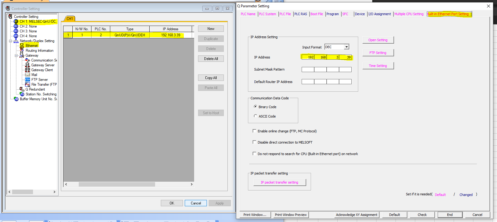
Try check this setting.
From GXWorks
Parameter > PLC Parameter
From GTDesigner
Common > Controller Setting
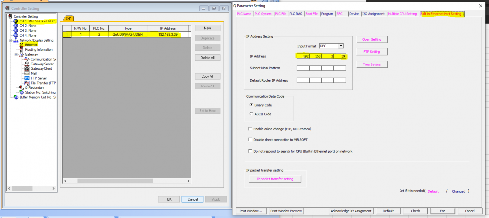
-
Found the solution for this.
Check for trigger device.in numerical input setting.
Make sure the device is ON and you good to go.
Normally this was setup due to make sure only one HMI can operate the SP. There are 2 HMI for this system located at different places.
-
Hi guys.
Somehow I cannot open keypad for numerical input from simulation.
The HMI is using user-defined keywindow for keypad.
Setting as below:
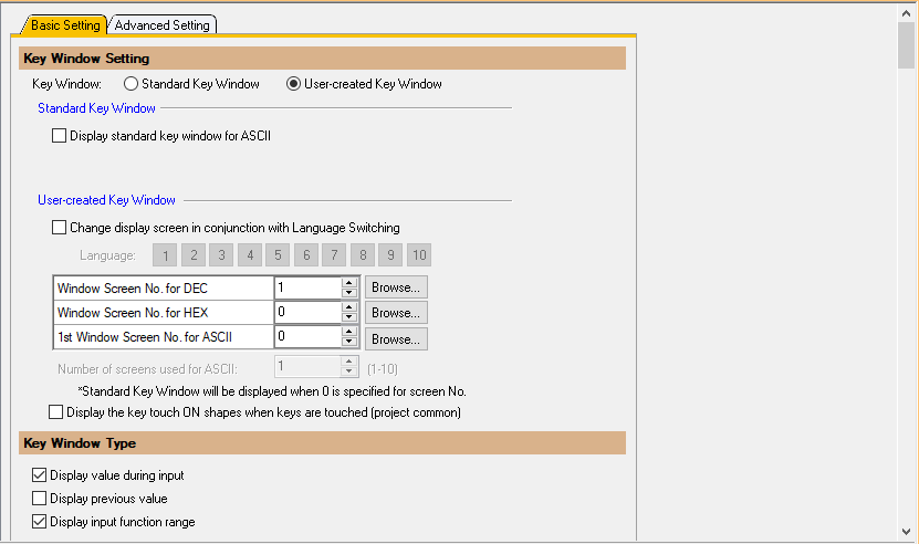
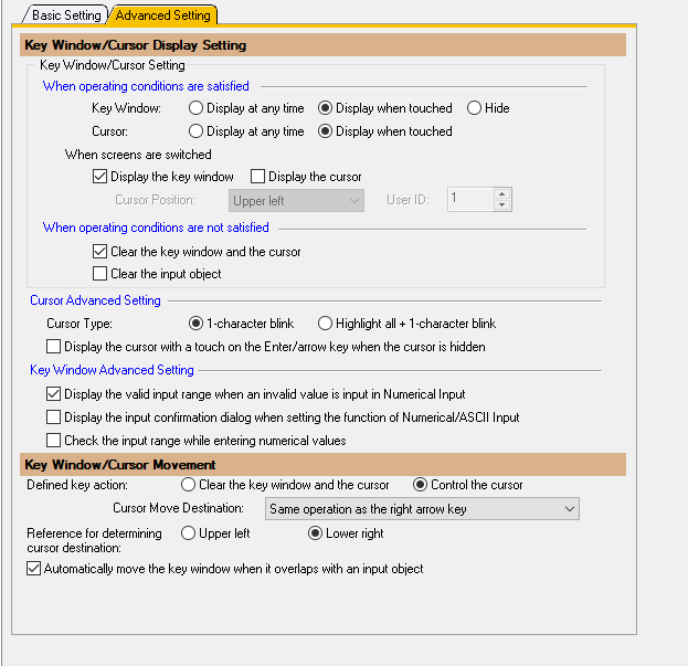
Any advice on what to check? I have been messing around with the setting with no luck.
Thanks!
-
On 5/31/2022 at 1:50 PM, Gambit said: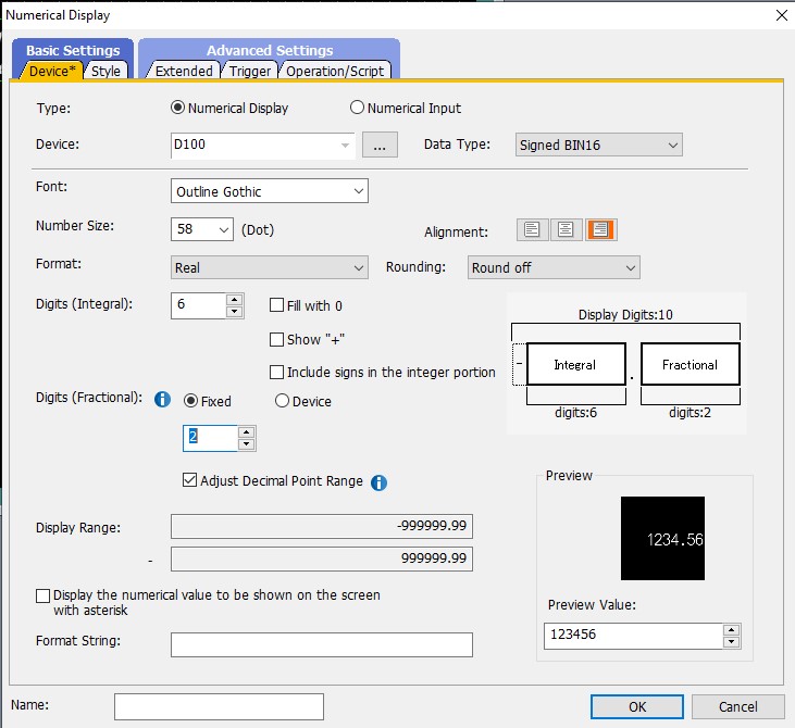
In this example you can see that the Data Type is Integer (signed 16 bits) but the display format is Real.
with the Digits (fractional) you can choose the decimal point location.
In the preview you can see the result.
Thank you! WIll keep this in mind in future.
Btw, integer in PLC cannot read decimal right? They required two D register, how do I compared them in PLC with single integer from HMI.
Eg, from calculation, result is 1.35. Register at D1 = 1 and D2 = 35. How do I compare with SP from D3 = 1.35?
-
21 hours ago, Gambit said:Alternatively moist HMI have an offset gain function or can add a decimal point Like the Mitsubishi GOT.
This way you can keep working with integer values in the PLC
Actually, I am using GOT2000.
Wonder how this one works, so that I may know some additional method.
This one will use 2 D value and show at HMI?
On 5/27/2022 at 6:58 PM, Theuns said:Hi See attached example
Thank you very much!
-
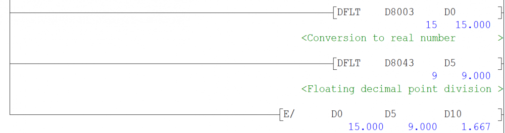
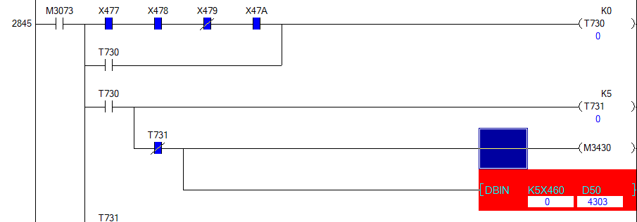
Hi guys,
So I want to divide two D value and comparing the result to setpoint and trigger alarm accordingly.
Most the time, the result of the division will come out with decimal point.
I am not familiar how to deal with decimal, floating, integer, etc before this.
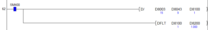
I try to do as below, actual result is 1.666.
D8100 - 1 , D81001 - 6
How do I properly put decimal value in D and to show in HMI?
Thanks!
1 person likes this -
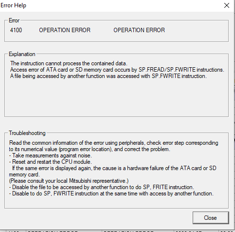
On 5/19/2022 at 4:24 PM, Gambit said:It's a command for reading values from a csv file from a CF flash ATA or SD card.
You only get the error if there is no SD card.
The instructions are FREAD & FWRITE (sp.fread sp.fwrite).
But if these instructions are not used in the program it is strange you are getting this error.
I believe there is no SD card attached.
Any advise on what should I check?
Some background,
1. There are around 7 PLC connected together through MelsecNET.
2. All PLC indicate this error. ERR LED lit up but not affecting sequence.
3. LED ERR will turn off after reset and come back on later, maybe after the instruction trigger.
-
53 minutes ago, Gambit said:An ATA card is a type of CF card which could be used with the first series of Q series CPU's. Now SD cards are used.
The error should only occur when File read or File write command is used. Isn't this instruction below the screencapture you send?
Hi Gambit,
Thanks for you reply.
What do you mean by File read/write? Is it the same as normal read/write like "MOV D1 D2" or is it read/write to/from ATA card?
Sorry I am not familiar with this instruction.
Btw, why there is error when read/write command is used?
Thanks.
-
Hi guys.
I found error on PLC and from PLC diagnostic I found this Operation Error 4100 as per attach picture.
FYI, there is no SD card mount onto this PLC. I wonder what is ATA card.
This error wont affect the operation. Any advise on what to check?
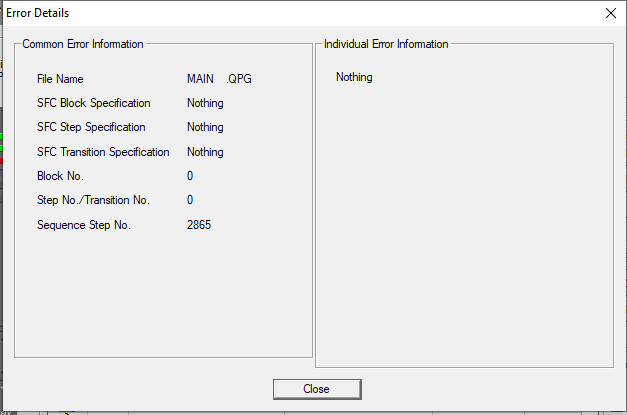
This ladder is pop up when I clicked, error jump.
Thanks.
-
I never use/cant understand structured ladder.
Btw, try click Error Help, PLC will tell you whats wrong. Btw, I think, with minor error, your PLC should still be run as usual.
-
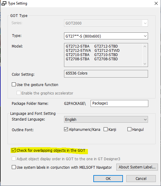
On 4/21/2022 at 2:40 PM, Gambit said:You probably have an Overlap of Objects somewhere on the page.
under =>type setting => options => you can select check for overlapping objects
Thanks! I have uncheck the "check for overlapping objects" and the error is gone.
I try to find the said overlap object but cannot find any. Is there any better way to do it?
-
11 hours ago, WattUp said:Project navigation PARAMETER > PLC Parameter.
Then select the device tab.
Any data points listed under Latch 2 Start - End will remain through power outages / reset.
Thanks!
So will need to set Start-End address for the Latch 2?
If none is set meaning all register will be clear upon PLC reset right?
How about if the value is set (Numerical input) in HMI, will the value be reset? I have encountered some reset and some doesnt. Or the HMI have their own memoy?
-
On 3/3/2022 at 3:38 PM, VeeB said:A reset is similar to a power down/up secuence. A reset is neccessary to make new parameter settings failed for instance.
Programm is reset and internal relay's and registers are reset to initial ("0")Battery backed / Latched relay's and registers retain their value. (the range differs according to the used CPU)
How to check for battery backed relay and register?
-
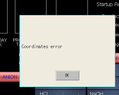
Hi guys.
I was getting Coordinates error popped up everytime I tried to go the page.
If click OK, everything is normal and can operate as usual.
Just wondering how to eliminate and what causing this error.
Thanks!
-
Hi guys,
I always wondering, what is reset when reset button is click?
Does the setting from address D from HMI will be lost?
Does internal memory of PLC is reset?
Anything thats not reset?
Or just reset sequence?
Thanks.
-
Hi guys,
So I found that CH2 on Q68ADG is abnormal.
Whenever I short the termination, the digital value goes max to 4096.
Input is set to 4-20mA with normal resolution.
I tried to simulate 4mA-20mA but still same result.
Does this mean the CH2 is damaged? Equipment at site is normal and give 5mA signal.
Thanks!
-
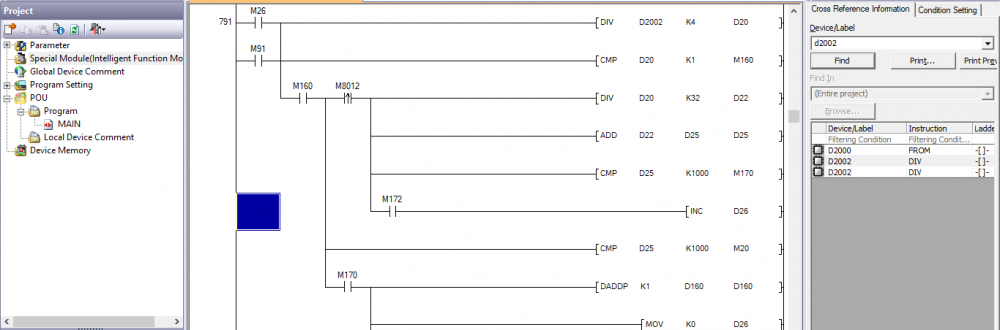
Hi guys.
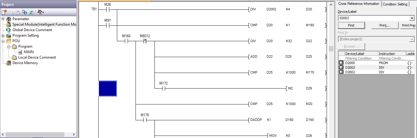
So I try to read FX3U PLC using GXWorks2. There are 2 unit of Analog Input module installed but I cannot read the module from GXWorks2.
I am trying to find input mode setting in the program to define the AI range but cannot find any. D2002 is the AI channel. I back-traced from GOT address.
Any advise?
Thanks!
-
21 hours ago, Gambit said:I Haven't checked that but i think that should be possible to read that information.
I updated the version of GXWorks2, now its all OK! Thanks again mate.
-
53 minutes ago, Gambit said:For this, I required to connect to master or slave? Or required to open any slave projects and connected to master? I am using USB to read the PLC
Yes , that was my example. So connect your USB to your master and select in the transfer setup USB connection as you would if you wanted to connect to that PLC.
Check comms and than do the next stepI am struggling to find network no for the melsec net and station no for the slave PLC. Is there anywhere I can check from Master PLC parameter setting?
These settings have been made already in the PLC network paraneters. (check those)
Thanks! Got it! Thank you very much!
But just to confirm, when I read thru melsecnet, I cannott read intelligent module, is that normal case?
If read direct read from USB, I can read the intelligent module.
-
On 3/5/2021 at 4:19 PM, Gambit said:Sure, Open one of the slave projects. Create a new connection destination and call ot ViaMaster or something like that.
Now you should get the transfer setup. First make the same settings as you have for your master coms (usb... ethernet... ).
press the connection test button. It should say that is found the master PLC.Now on the third part (other station setting) change the No specification to other setting. (the second item/picture)
Now the next row should become available choose the first picture (..........10/H).
Click on tne picture and enter the network number you have setup for your Melsecnet and the station number of the slave which you want to communicate with.
press the connection test button. It should now be connected to your slaveThanks!
Some question tho;
"Sure, Open one of the slave projects. Create a new connection destination and call ot ViaMaster or something like that.
Now you should get the transfer setup. First make the same settings as you have for your master coms (usb... ethernet... ).
press the connection test button. It should say that is found the master PLC."For this, I required to connect to master or slave? Or required to open any slave projects and connected to master? I am using USB to read the PLC.
"Click on tne picture and enter the network number you have setup for your Melsecnet and the station number of the slave which you want to communicate with.
press the connection test button. It should now be connected to your slave "I am struggling to find network no for the melsec net and station no for the slave PLC. Is there anywhere I can check from Master PLC parameter setting?
Thanks again!
-
17 hours ago, Gambit said:yes that is possible
Could advise on how to do? By read/write I didnt mean for read/write the IO but the program/parameter, ie to modify slave 1 PLC from master PLC.
Thanks!

GX Works2 installation problem
in Mitsubishi
Posted
Thansk!
2nd method works for me.