

PeterParker
MrPLC Member-
Content count
12 -
Joined
-
Last visited
Posts posted by PeterParker
-
-

Here what i mean regarding lines over my image.
My other part deletes the use of FLX-1
-
1 hour ago, AndreasW said:Hi PeterParker,
you can add your image (bitmap, jpeg) to the user library and then use a normal Bit-/Word-Lamp or a Switch/Button control object.
There you only have to change 'shape' attribute and select your image from the library, and you also can use the
control display/hiding feature.
If you need to show/hide a lot of images at the same time, you can use the 'Parts'-Functions instead of showing/hiding the individual images.Thanks! That solved that, but has presented a new issue.
Once converted to a bit lamp, I can no long have lines drawn on 'top' of it. My image is a part holder, holding 2 parts with 3 holes in them each. I drew lines from all 6 holes, to a lamp showing the status of all the holes individually.
Now my lines are behind the newly converted bit lamp. The reason I need to control displaying/hiding is I have another type of part (with less holes) that i wanted to switch between when the machine mode changes. The image will change, as well as some of the hole status' and lines disappearing.
Any way around not being able to have lines drawn over it now?
Appreciate your help!
-
Hey guys,
I'm familiar with using the "Trigger" tab and using " Control displaying/hiding" for lamps, text, lines etc..
But I just cant figure out how to do that with an image I've brought into the project.
Double clicking the image gives me a pup up called Bitmap Attribute Change with "Open image data in Paint", and "specify a transparent color for image data" as options to click.
Seems like the image need to be converted to something else, then i can do it?
Appreciate any help I can get! Thank You!
-
Turning off language switching fixed it.
Thank You!
-
Oh man,
I will look at that.
I was a little overwhelmed using the comment setup for language switching, and i need that for this job. So i decided to duplicate my screens and do Spanish variations instead. My language switching is then done by 2 buttons that are flags, that switches between my groups of screens. I'm too used to language switching on Vijeo screens which is built into the text input, this is my first Mitz trying to do that.
I forgot that the first thing i did was enable that Spanish, and then deleted the other column after an hour of frustration.
Thank you so much Gambit!
-
Project attached
Screen 9 is my temp screen while trying to figure it out
Thank you so much Gambit
-
Hello!
Im trying to set up Alarms on my project using GT Desisgner 3. My GOT is a GS Series, and my PLC is a FX5U.
I usually just do a multi state lamp with descriptions for what's happening on the machine, but this system is much more complicated, so id like to do an alarm screen.
I found a few sample projects, as well as tried both the Simple and User alarm tools on my own. However once everything is set up, when an alarm is triggered, the comment for that alarm is missing...
The alarm time of occurrence, as well as turning green when its resolved all works on the screen, but i cant figure out why my comment doesn't show up.
When in my project, all the "previews" of my comments show up great and are all there, just not on the screen itself...
Any help would be greatly appreciated! Thanks!
-
Just now, Gambit said:CC-Link is a global name.
- You have standard CC-Link
- CC-Link IE Field basic
- CC-Link IE Field
There are also the safety Variants and of course TSN
Anyway the module you are referring tot is for a CC-Link IE field Network (1Gbps)
You are using CC-Link Ie field Basic I expect
Ah ok. That is correct.
-
4 minutes ago, Gambit said:Sorry to have to tell you this but this type is anybus converter is a cclink is field slave. This would mean your fx5 would have to be the master. There is no master module for cc link or field for the fx5 just a slave.
But I'm sure there is a network which is supported
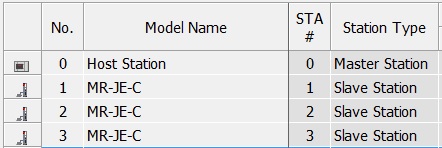
I don't quite know what you mean here, sorry for my inexperience, When i open my CC Link Config, My FX5U is set as the Master Station.
-
I have a Mitsubishi FX5U-32M with 3 MR-JE-40C servos. Our system will be used in a robot cell, and needs to convey some information to the customers system, which is this EtherCAT side of things. They want to know RPM, torque values, position ,etc, of things on our system..
Our Mitsubishi supplier recommended an AnyBus X-Gateway (AB7961).
They have a few YouTube videos on configurations, but unfortunately none on the Mitsubishi side i found. I've only been using Mitsubishi for a little over a year, but know my way around GX Works 3 pretty well. I come from the Rockwell world with EDS Files and tag based setups, and for the life of me cant figure out where to start with this AnyBus.
I've gone to the support page, got all the downloads and software, and gotten online with the Anybus. As far as beginning to setup the Anybus in GX Works side, to setup what registers i want to send, im lost...
Anyone out there have experience with this sort of thing?
GT Designer 3 Display/Hide an Image
in Mitsubishi
Posted
I ended up putting the lines on the image itself, and it looks pretty good.
Thanks for your help!