

Neverov
MrPLC Member-
Content count
62 -
Joined
-
Last visited
Posts posted by Neverov
-
-
4 minutes ago, Gambit said:It's an end of life product.
I can provie you with the latest installer if you have a installation code for it.
Or you can ask Mitsubishi Europe
Please share, I have a key. I do not know from which specific version (key). But I think that it will fit the latest version of the program.
-
I can't find the IEC Developer licensed installer anywhere.
I checked the global, European and Japanese Mitsubishi sites.Why isn't he there? Can someone suggest where to find it?
-
1 hour ago, AndreasW said:Hi Neverov,
you can find this manual at
https://dl.mitsubishielectric.com/dl/fa/document/manual/plc/sh080040/sh080040s.pdf
for a list of other manuals for L-Series:
https://www.mitsubishielectric.com/app/fa/download/search.do?kisyu=/plcl&mode=manual
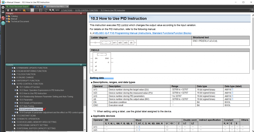
The problem is that everywhere in the manuals there was no PID function that does everything with one function. They are complex and fragmented. I was only able to find a description of it here:
https://dl.mitsubishielectric.com/dl/fa/document/manual/plc/sh080809eng/sh080809engx.pdf
-
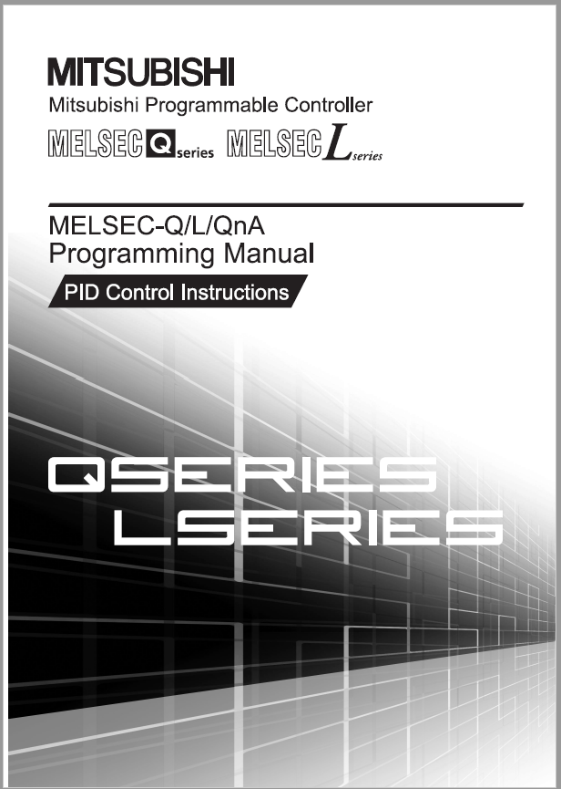
6 hours ago, Theuns said:Hi Neverov
There is a separate manual for PID.
See attached pic. I can send it to you via email
Regards
Thanks Neverov.Aleks@gmail.com
Can't find it in search. By this name I constantly stumble upon another instruction, as in the e-Manual Viewer.
-
The only place where it is told about the PID controller, but there is no "PID" function block. Or am I blind ((
Or MELSEC-L does not support such a function??
-
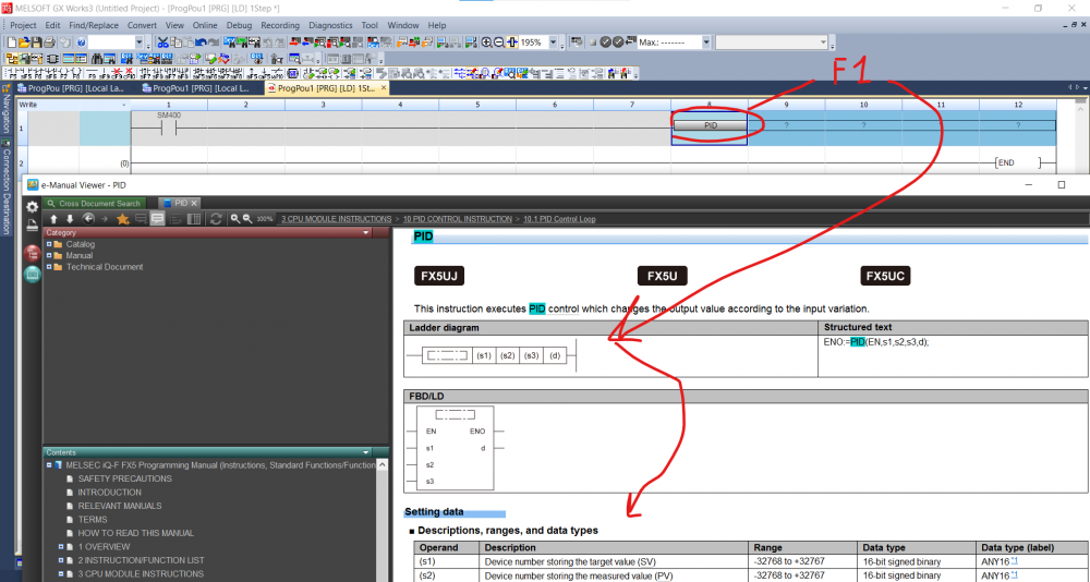
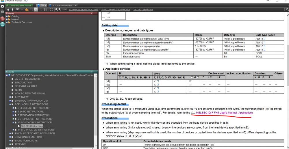
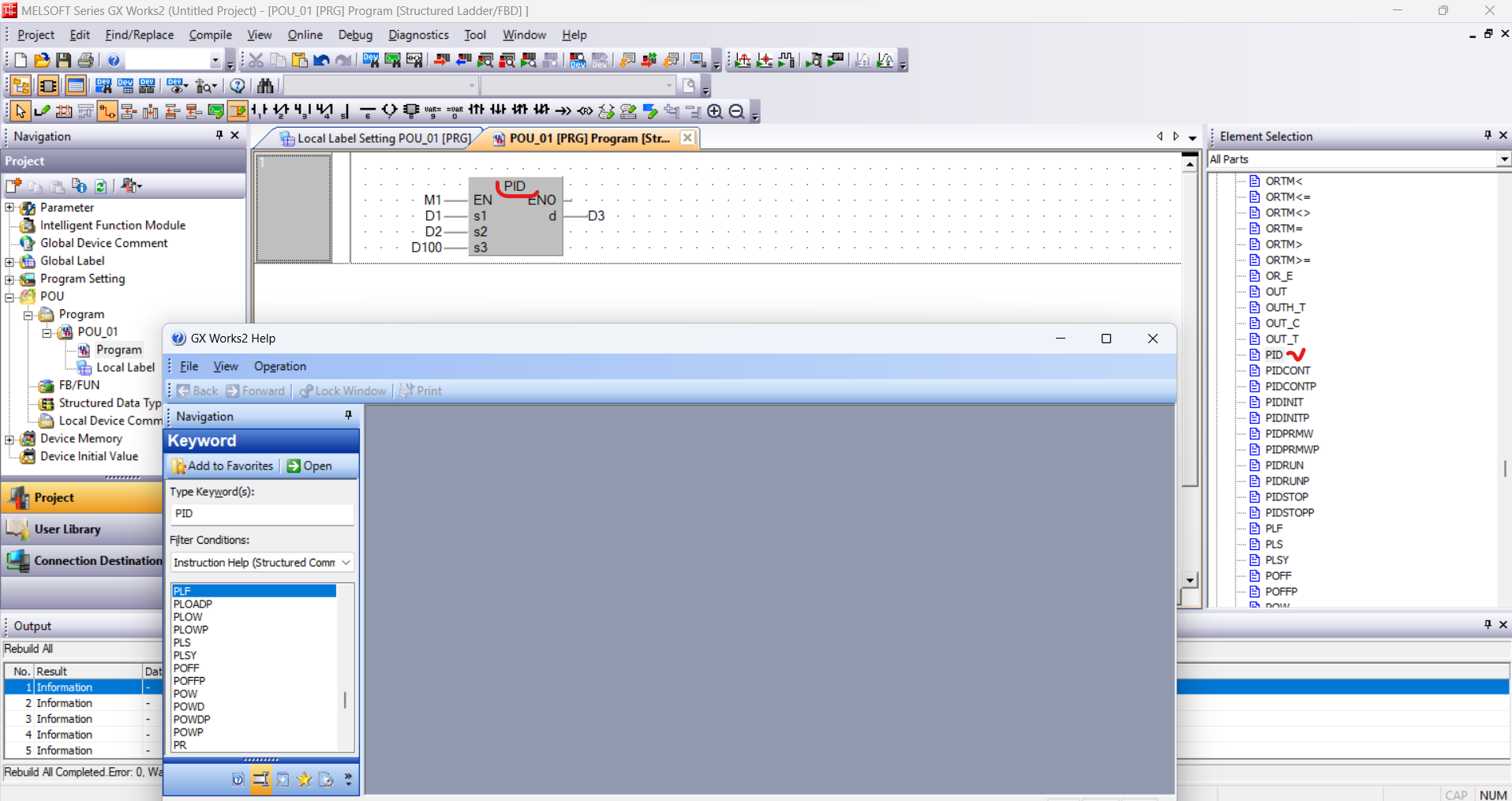
Hello. I have worked with PID controller in IQ-R and IQ-F series. It took to apply in MELSEC-L. I found the same function block, but I can't find the documentation for it anywhere. In the "e-Manual Viewer" it finds a combination of PIDRUN, PIDINT and the like, but there is no description for the "PID" function block.
Help find a description.
-
12 hours ago, Gambit said:you're program creation was for just ladder. You should create a program in structured instead and read out the program againhttp://.
That is, before reading the project, create an empty project ? And only then read?
Immediately after opening the program (without creating a new project), I clicked to read the project.

-
14 hours ago, glavanov said:What is your ver. of GX W2 ?
-
Unfortunately I am not familiar with Node Js. Reading from writing differs only by the function code inside the ModBus message. I always look at this cheat sheet when working with ModBus.
-
A working controller FX3 on factory. It was necessary to subtract the project (using GX Works2) to save it in case of a PLC breakdown. Never faced such warnings before. What could it be because of? How to make sure that the read project can be used in the event of a PLC breakdown?

-
FX5U have ModBus TCP (slave/Master). Maybe it will be easier on it? For ModBus TCP (slave) it is not necessary to write a program inside the PLC. In the "Enable" settings and you're done.
2 people like this -
5 hours ago, _Pavel_ said:Dear All,
I have iQ-R R08ENCPU and I declare variables as var_global_retain but they are not actually retained
The battery is OK, is particular, the PLC clock is OK
Need strongly any ideas, where am I incoirrect
Thanx.
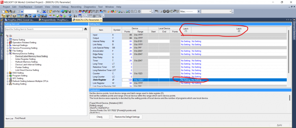
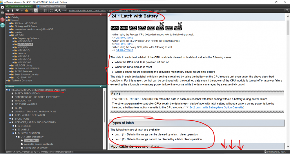
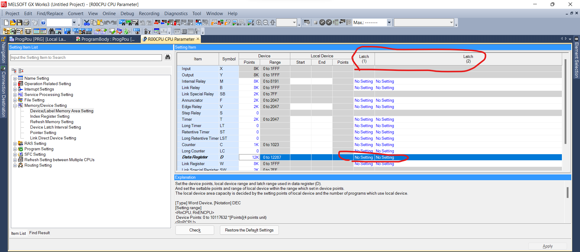
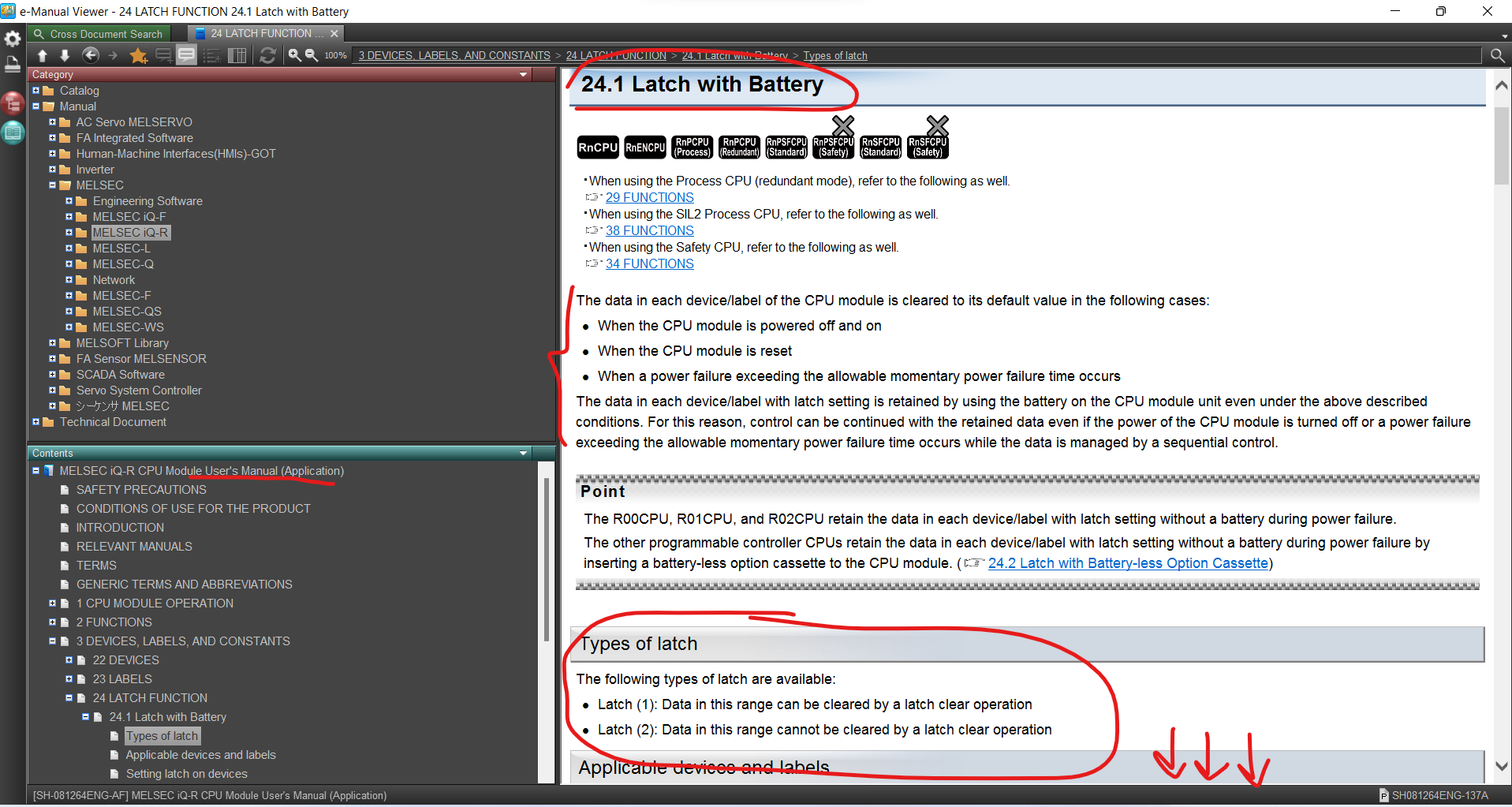
Become familiar with the following concepts:
- Latch (1)
- Latch (2)
-
8 hours ago, WGL said:HI, HOW CAN I WRITE PID INSTRUCTION IN LADDER LOGIC FOR STEAM CONTROL VALVE BY USING PNEUMATIC REGULATOR
Need more CapsLock.
-
5 hours ago, RikiWatasuta said:Thank you in advance for answering my question.
but I haven't been able to solve the problem.
I'm very happy if you can show me how in detail so that "2 WORD" becomes "1 FLOAT"
for example if D0 = 0X0002, and D1 = 0X23FF. I want the output to be D2 = 0X000223FF.
I'm still really a beginner in the PLC world
Here's an example.
Can anyone have a more elegant solution?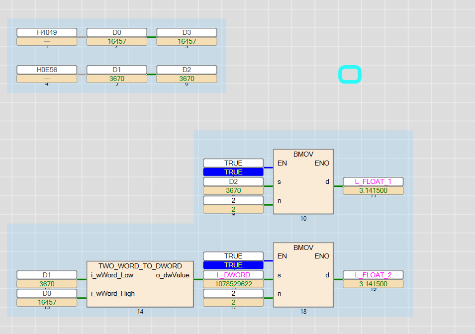
-
On 02.07.2021 at 0:27 PM, RikiWatasuta said:Hello all. First time post in this forum.
I am hoping someone here can offer some advice or a solution to a problem I am having.
I have a Modbus water meter from chinese that connected to my FX5U with ADPRW Instruction, but i have a problem. The cumulative flow from water meter is a 4-byte hexadecimal number, with the high bit first and the low bit last.
I want the output from the PLC is real number FLOAT. can someone in this forum help me to combine 2 different WORD and create a single FLOAT.
Here I Attached document from water meter.
Thank you,
BMOV
https://forums.mrplc.com/index.php?/topic/40236-dword_to_real/
-
17 minutes ago, ClaytonOLeary said:I am sorry Neverov, I'm not too sure what you mean by that.. just looking for some advice as I am new to HMI's and PLC's and currently doing work experience.
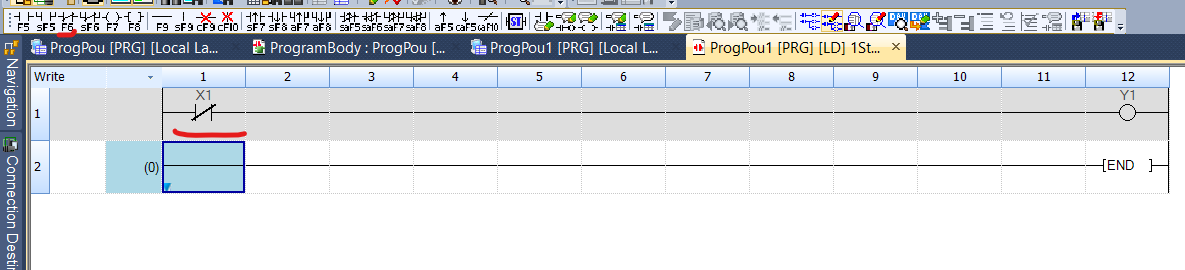
Is this what you want?
-
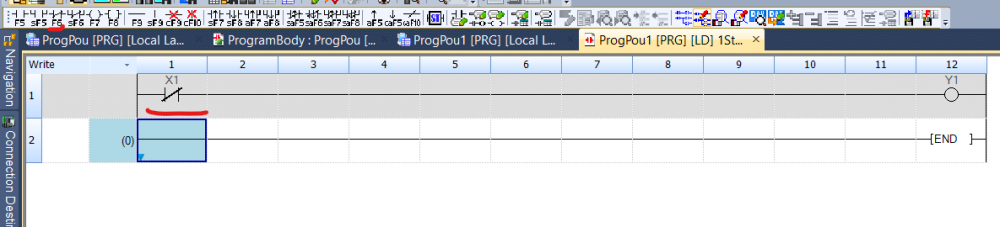
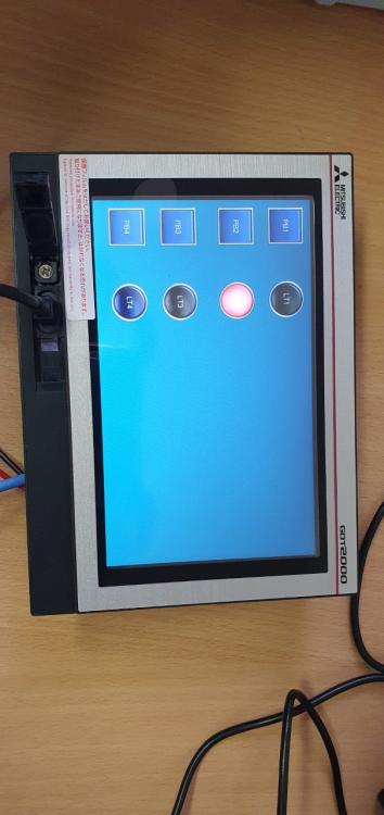
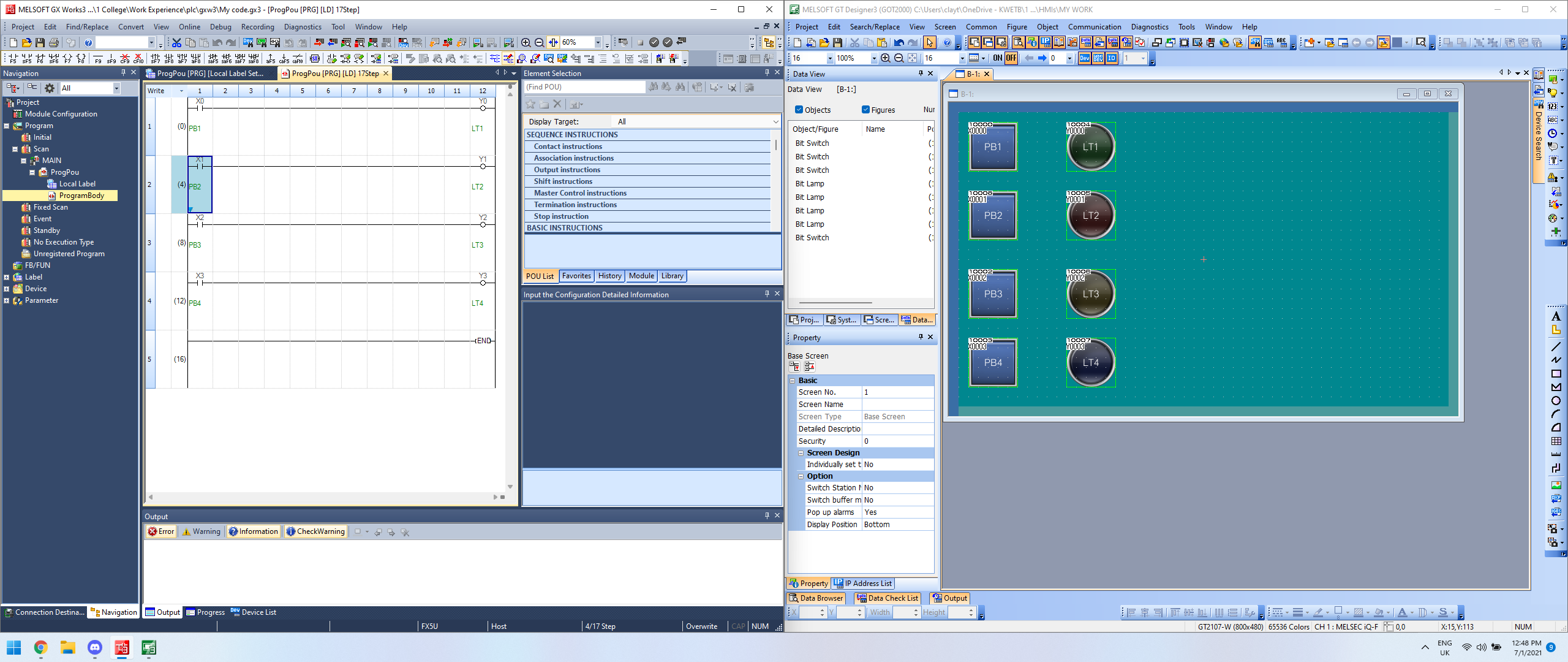
16 minutes ago, ClaytonOLeary said:Привет, ребята, я использую HMI GT2107-wtsd и ПЛК FX5U-32M с gx works3 и designer3, я установил простой код релейной диаграммы, чтобы проверить, что все работает, но я не могу открыть нормально закрытый контакт, когда я нажимаю кнопку на HMI и выключить свет? на скриншоте ниже показан код и кнопки HMI, когда вы просто смотрите на экран HMI, все индикаторы должны быть выключены, за исключением индикатора номер 2, поскольку он подключен к нормально замкнутому контакту, и я хочу, чтобы он открывался, когда я нажимаю кнопку на HMI рядом с LT2 (индикатор 2). Кажется, я не могу заставить его работать ...
пожалуйста, помогите, спасибо.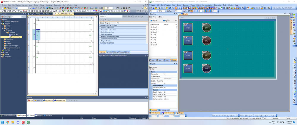
Throw off please projects, too lazy to type yourself.
-
41 minutes ago, ClaytonOLeary said:I had a look through all those links thank you for the help but what these are showing is how to simulate them together but I am looking to actually physically use the HMI to control the PLC if that makes sense
I don't have a GT2107, but these projects should work.
-
34 minutes ago, ClaytonOLeary said:I had a look through all those links thank you for the help but what these are showing is how to simulate them together but I am looking to actually physically use the HMI to control the PLC if that makes sense
https://www.youtube.com/watch?v=q7O7EeNBTZA
GS2107 differs from Gt2107 with stripped-down functionality. Everything else is the same.
When writing a project to the panel, select USB instead of Ethernet
-
-
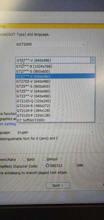
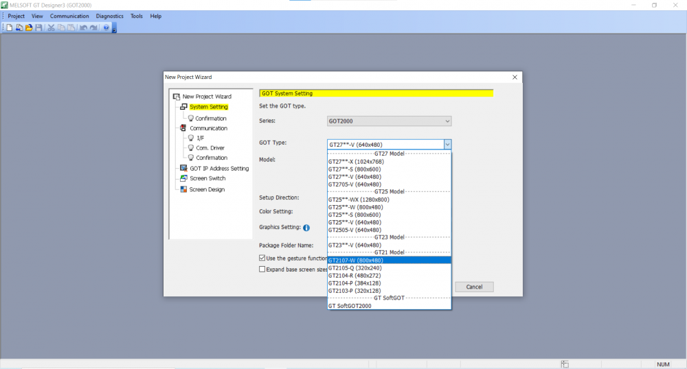
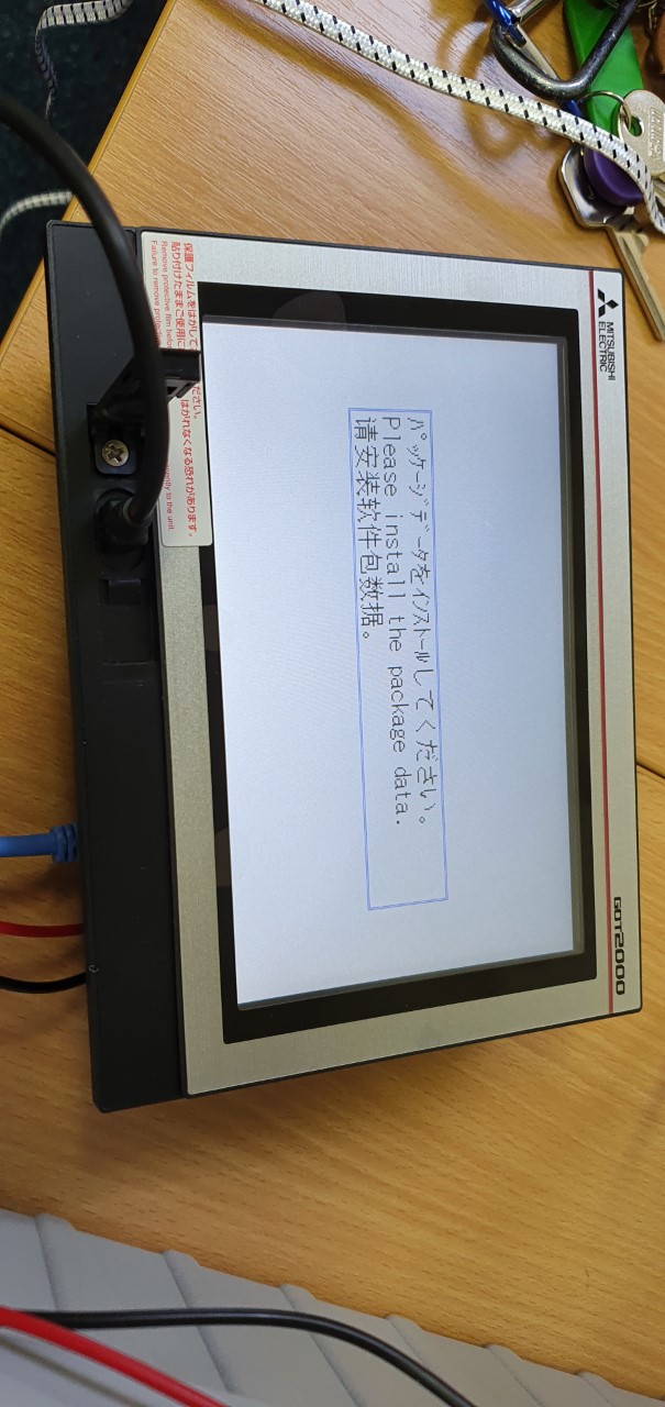
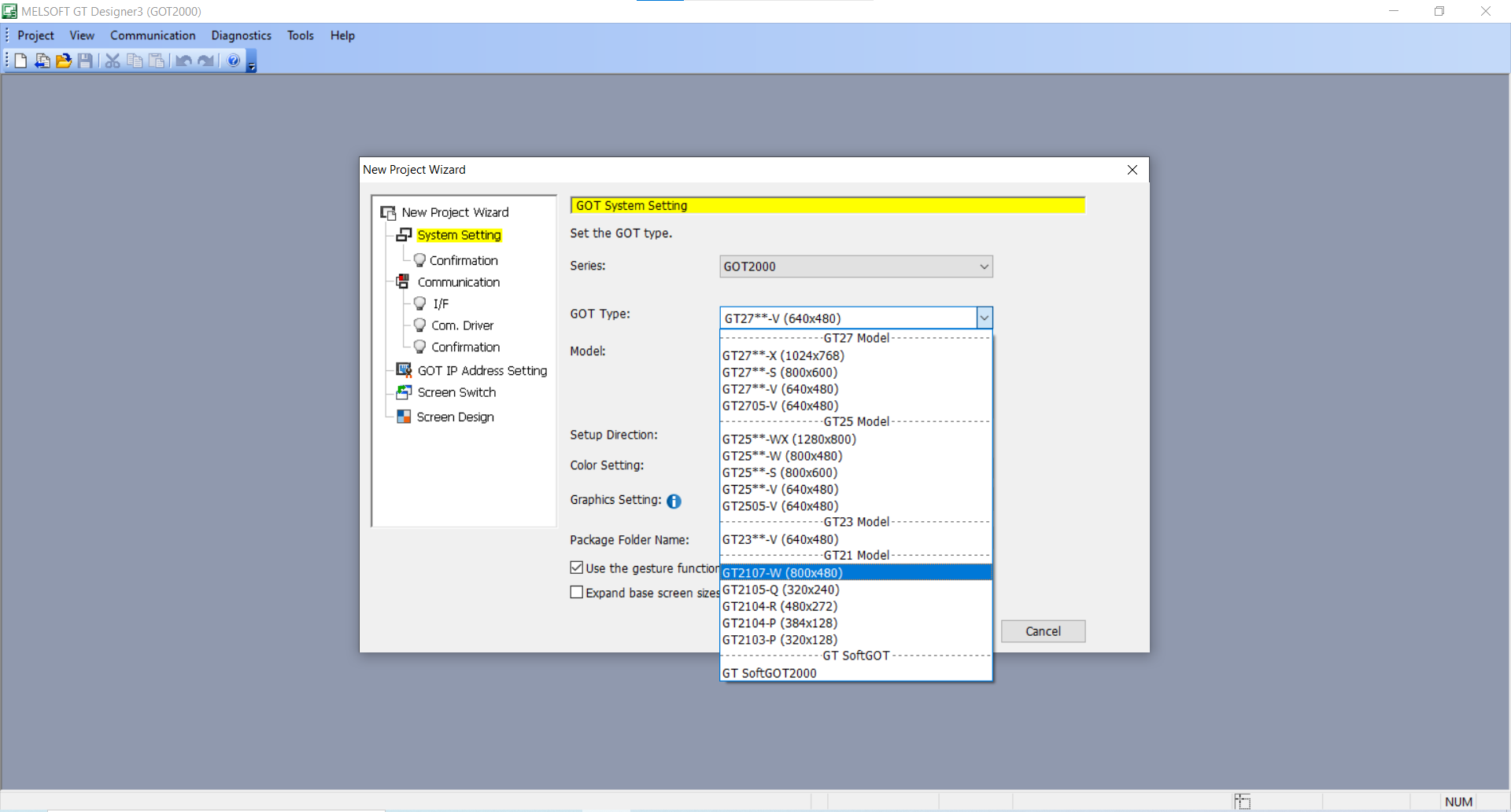
33 minutes ago, ClaytonOLeary said:Привет, ребята, я просто ищу помощь, если возможно, я пытаюсь настроить HMI (2107-wtsd), но в GT Designer3 нет этой модели и нет моделей 2107 в раскрывающемся списке типа GOT. Как я могу показать свою модель? Я попытался установить тип GOT как G2105 и GT softGOT2000, и это не сработало, HMI отображается на белом экране с данными установочного пакета, но я не могу этого сделать, если он не находится в раскрывающемся списке GOT, правильно?
Я приложил несколько фотографий, чтобы показать.
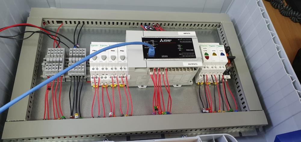
HMI подключен к PLC через Ethernet, а ноутбук подключен к HMI через usb
Я очень новичок в этом, поэтому мы используем испытательные стенды, поэтому, если что-то выглядит не так, мне очень жаль
Probably an old version of the program ??
https://www.mitsubishielectric.com/fa/download/software/hmi/got/index.html
-
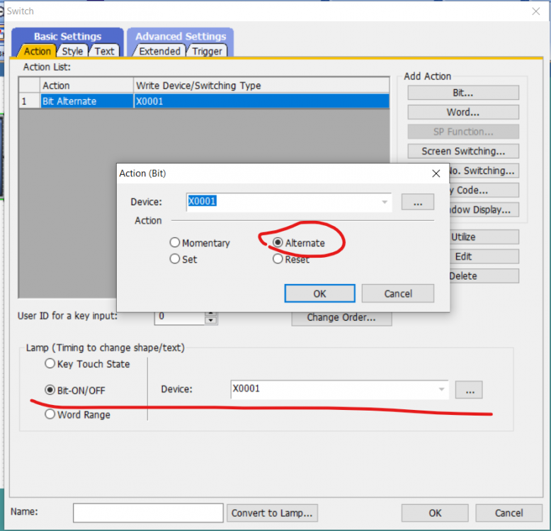
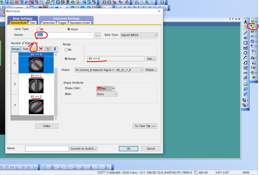
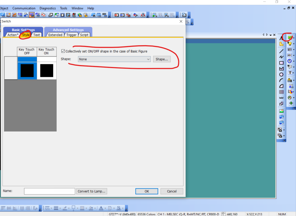
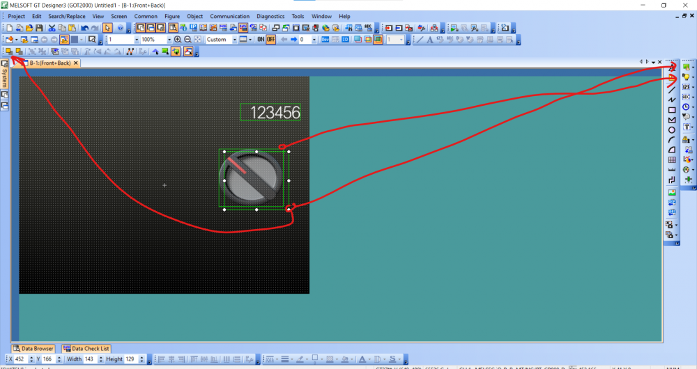
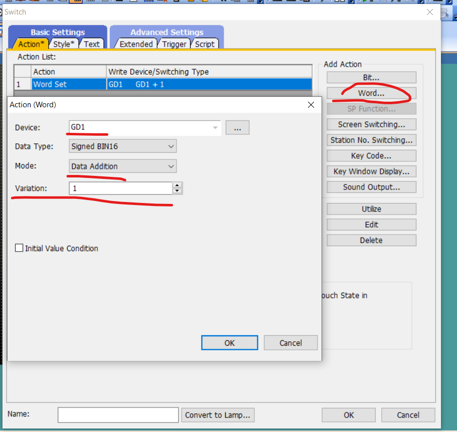
48 minutes ago, PLC Rookie2021 said:I am newer to GT designer. Ive used it a couple times years ago but I cannot figure out how to create a 3 position switch and cant really find any info on it? Is there a special way to set a switch up so that eveytime the operator hits it it changes the state or picture of the switch from left to up then to right and back? im sure its probably just something that im not seeing in the properties menu but any input would be greatly appreciated.

Take out the light bulb first.
Then on top of it a transparent button.
But in the plc or in the panel scripts, you need to reset the switch counter. Because the button will count until it overflows in a circle.Or hang up the M register on the button.
And in the PLC program, add or subtract the number of lamp output to the screen.I don’t know any other options.

 1 person likes this
 -
In any unclear situation, reinstall Windows ;)
The length of the path to the executable file must not exceed (I don't remember how many) the number of characters. Copy the installation archive (folder) to the root of the C drive
-
Try clearing / formatting the CPU memory.
And upload a clean project. With default settings.
If it does not help, wait for a response from more experienced users.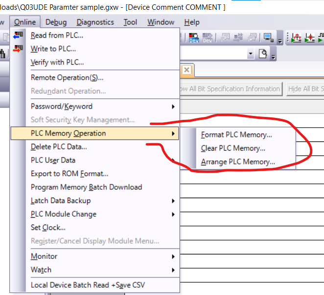


MELSEC-L PID Control (Function block difference / limit)
in Mitsubishi
Posted · Edited by Neverov
Hello. I will be very grateful for your help!
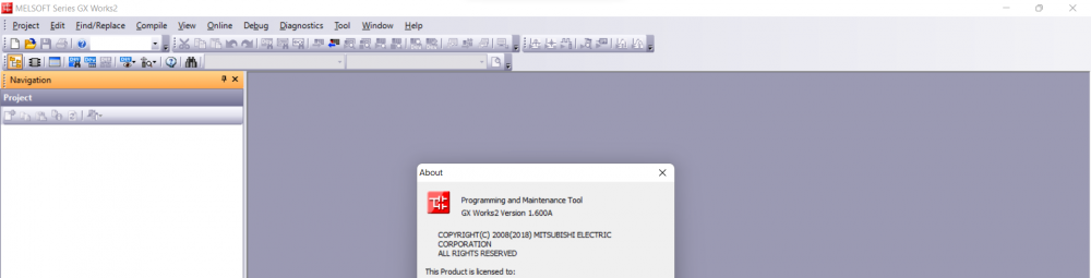
There is a MELSEC-L controller (GX Works2), it is necessary to implement PID controllers.
Question:
Is it possible to work with 33 or more PID controllers at the same time?
Why I have this question:
1) There is a
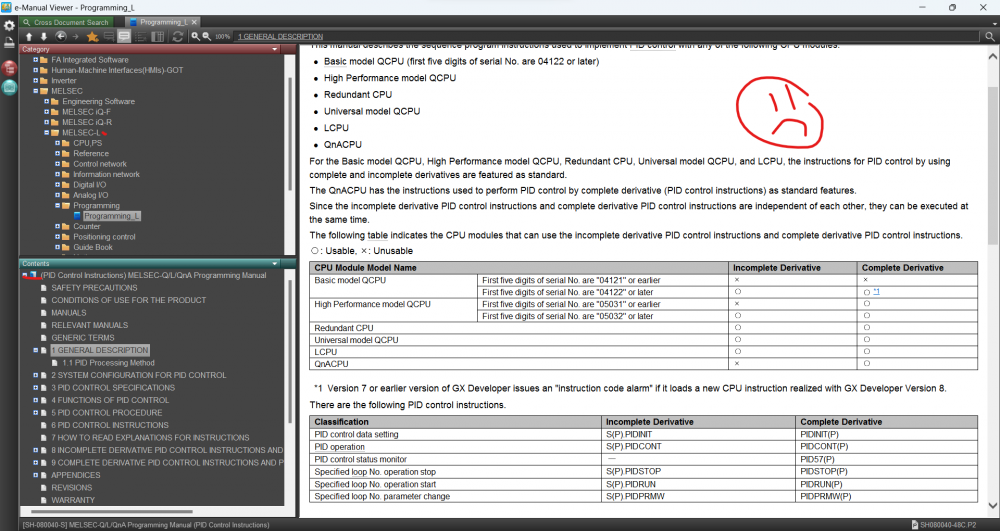
dl.mitsubishielectric.com : MELSEC-Q/L/QnA Programming Manual (PID Control Instructions)
On page №16, there is a table that says "Number of PID control loops: 32 loops (maximum)".
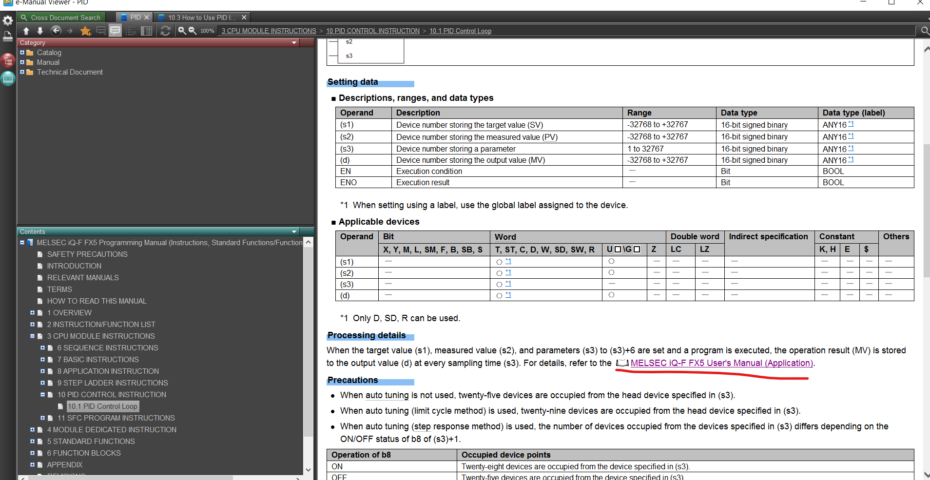
2) In the
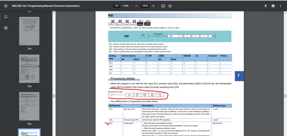
dl.mitsubishielectric.com : MELSEC-Q/L Programming Manual (Common Instruction)
On page №737, there is a description of the "PID" function block, where there is no limit on the number of uses. I saw a note about the CPU serial number.
3) On the Mitsubishi website there is a library fb-cpu-pid_v110l_e.zip
www.mitsubishielectric.co.jp : fb-cpu-pid_v110l_e.zip
I can't figure out if there's a limit to how many PID controllers can work at the same time in a program. What is the difference between PID controllers (from the points above)?
p.s. I liked the pid regulator from point №2 the most.