

Mendon Systems
MrPLC Member-
Content count
490 -
Joined
-
Last visited
Posts posted by Mendon Systems
-
-
OK ... I see what you are after.
Whether that will work or not depends on how much inrush current those VFD's draw. I would not be at all surprised if you wiped out some fuses. Is there a way that you could power up the VFD's one at a time?
-
The way you described it you would be backfeeding the 1.5kva transformer through the secondary windings. Don't you have separate protection to isolate the devices on the 120 volt secondary?
-
The default IP address for the ETN is 192.168.250.node# (node number set on rotary switch). There is a small chance it might still be set to that IP address. If it is you must use a PC set to the same subnet to establish communication with CX programmer.
-
Sounds like your cable is missing one of the handshake jumpers. 4-5 should be jumpered at the PLC end and 4-6 & 7-8 on the PC end.
-
If you really need that capability then connect a second PLC and write a simulation program strictly for testing. I have done that before on the rare occasion where I needed active simulation.
-
One thing that will help is to break the project into separate logical tasks and create a program section for each task. That will allow you to arrange the program sections in a logical order even if you don't write them that way.
-
You still haven't told us which PLC you have, but assuming that it is reasonably current you should be able to use the ++(590) and --(592) instructions to manipulate the value in a DM or H register. Those register values will be maintained during a power cycle.
-
One thing to keep in mind when using immediate refresh:
The I/O point referenced by the immediate refresh can change state in the middle of a program scan which could mean that any rungs which reference the I/O point before the refresh get different results than those after the refresh. In most cases this won't make any difference, but there is a possibility that it could cause weird results in the logic which are extremely difficult to debug.
-
If it was powered by 208Y then no problem, but 230 comes in various flavors depending on where you are located. Some 230 sources have a neutral reference that provides 115 volts and others don't. There is also the infamous "wild leg" 230 that has one phase which is at 284 volts to the neutral. It is a whole lot safer to use a 230/120 control transformer.
-
Also check the DIP switch settings on your CPU. The settings of switch 2 (and 7 depending on the CPU type) can cause the CPU to try to load from a memory card on power up. Start with both switches OFF and configure from there.
1 person likes this -
I suspect that something in your logic is resetting the timer as soon it reaches zero.
-
Those two, along with several others refer to words A450 through A473. They are used as pointers by OMRON FB Library function blocks. The programming manual says "Do not change the content of these words".
-
It seems like you should be able to use the SRCH(181) instruction to do that. It will output the number of matches found to DR0. It is listed under Data Table Processing instructions in the W474 manual.
I suggest that you search for words containing zero. The SRCH instruction will give you a count of them in DRO. You can then subtract DRO from the total number of words to get the number of non-zero words.
-
What do you mean by "used"?? Do you want to count words which contain a non-zero value??
-
The SFCON and SFCOFF instructions in rungs 7 & 8 of task 0 control the operation of cyclic task 1.
-
Another way to look at it ....
The resolution of the AD042 will be 3000/12000 or 0.25 g increments. The accuracy depends on a lot of factors including the sensor, the analog module, and the power supply. The accuracy will generally be approximately resolution x 10 or 2.5 g in this case.
-
One configuration that hasn't been suggested yet is to replace that CPU13 with a CPU33 and add a CP1W-CIF01 if the HMI doesn't support an Ethernet connection.
-
As I recall there were a few versions of CX-P that would default to the Timer data type on PLC's that did not support it resulting in a compile error. Rather irritating!!
-
First ... I would suggest that the timer you are using is not long enough to do you any good (9999/100ms = 16.6 minutes).
Second ... If the rain sensor closes your roof, it will cause the timer to restart fro zero.
I suggest that you look into using the PLC's system clock and use a range of times that you want to allow your circuit to operate.
-
I think CXP is complaining because the SBN instruction immediately follows the SBS instruction (no main program content). Try adding a do nothing rung after the SBS and see what happens.
-
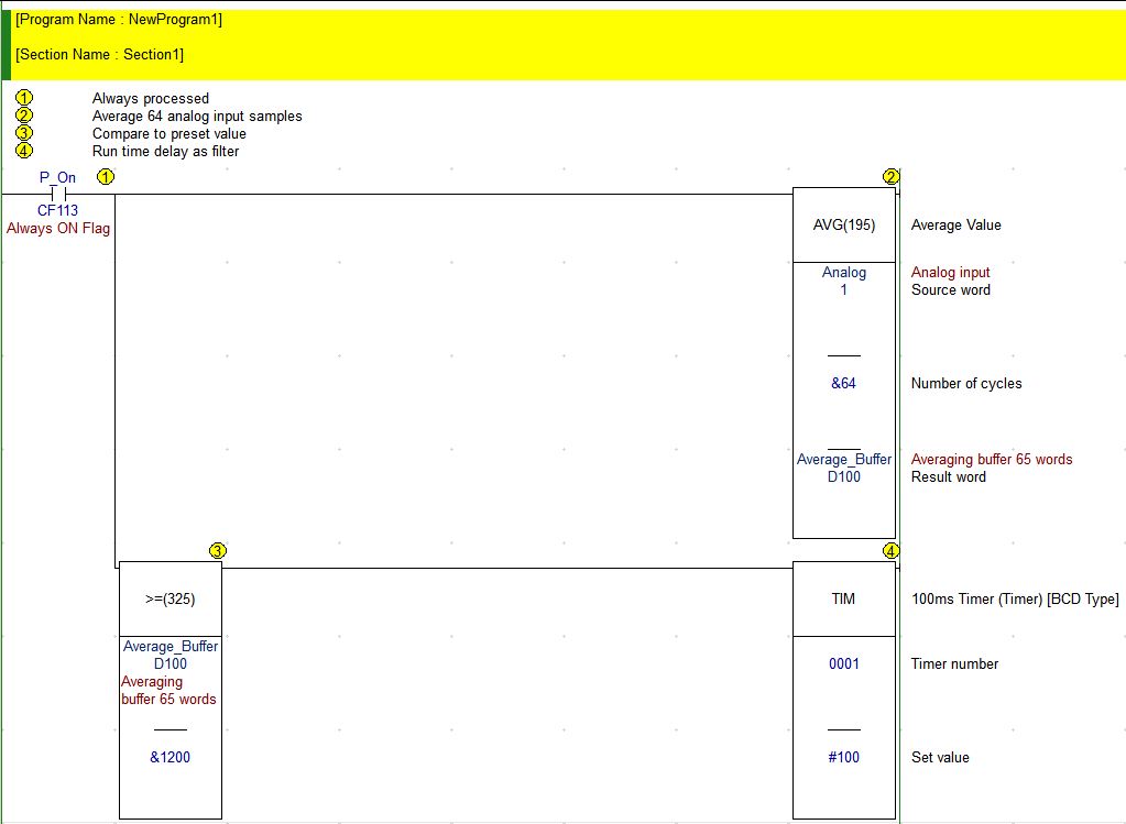
Here's the example above:
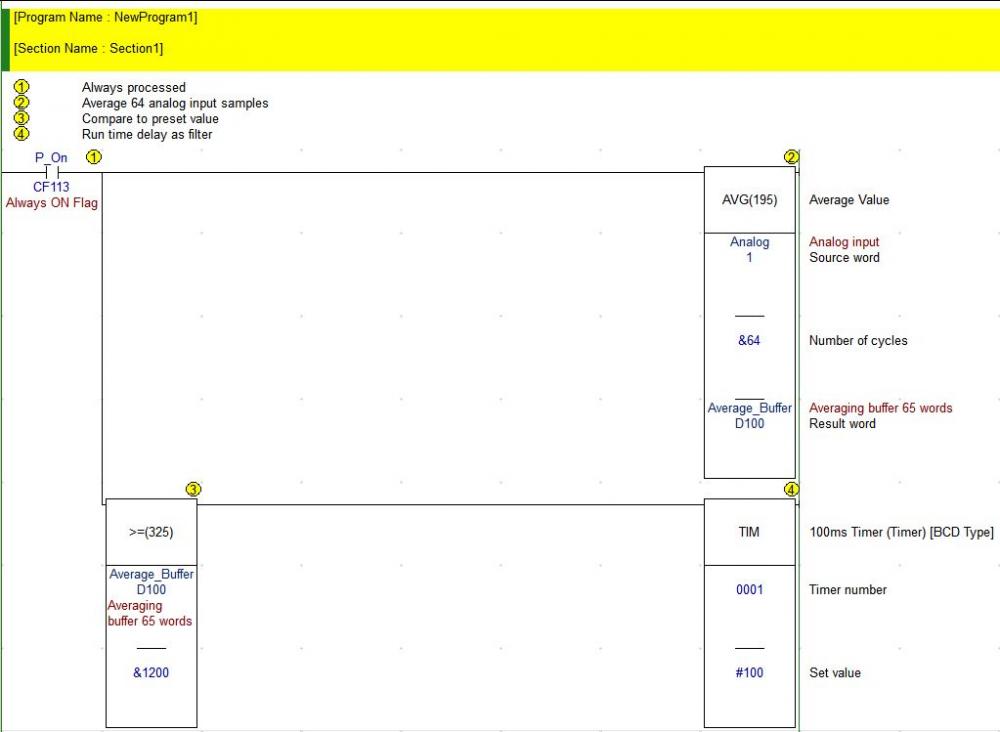
-
I suggest that you use something like the AVG (average) instruction to read the input data into a DM register. For example: If you are using input 1 and you want to average 64 samples into DM100 then the instruction would be AVG 1 &64 D100. You can then compare the value in the DM register to the value you want to use as a setpoint. Note that the AVG instruction uses a buffer so this would use up DM100 through DM165 for data.
If your setpoint was 1.000 volts then you can use something like an unsigned binary compare >= D100 &1200 to compare the averaged value to the setpoint and trigger your time delay. Even averaging 64 samples isn't a very long time if your program scan is around the typical 3 ms for a CP1L but with the time delay as a filter you should be ok.
-
The L14 only uses one input word (word 0) for the CPU digital inputs, so your AD041 module will use words 1-4 for the four input channels. You will want to set the input channel that you use up for 0-5vdc. The value of the input will range from 0 to 6000 for 0 to 5 volts. Your 0.4 to 2 volt signal will range from 480 to 2400.
-
If the CPU has a memory card and dip switch 2 is turned on, it will transfer the settings stored in the memory card at power up. Maybe that's what is happening??
Taking Screen shots
in Computer Help and Networking
Posted
I use a utility called Greenshot which allows you to capture any area of the screen you want and send it to a printer or save it as a file.