

Roze
MrPLC Member-
Content count
16 -
Joined
-
Last visited
Posts posted by Roze
-
-
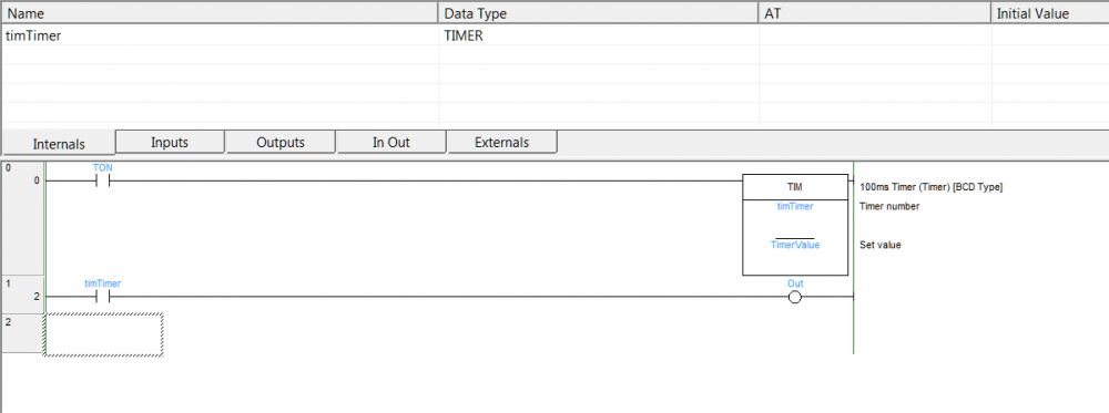
As promised, here is the solution:
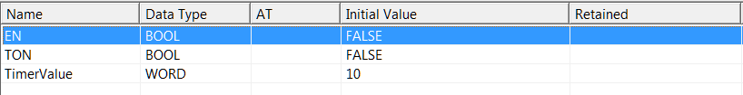
Input Variables:
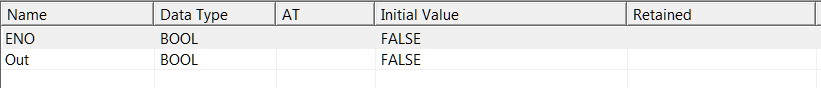
Output Variables:
And to call that from ST when programming for a CP1L CPU :
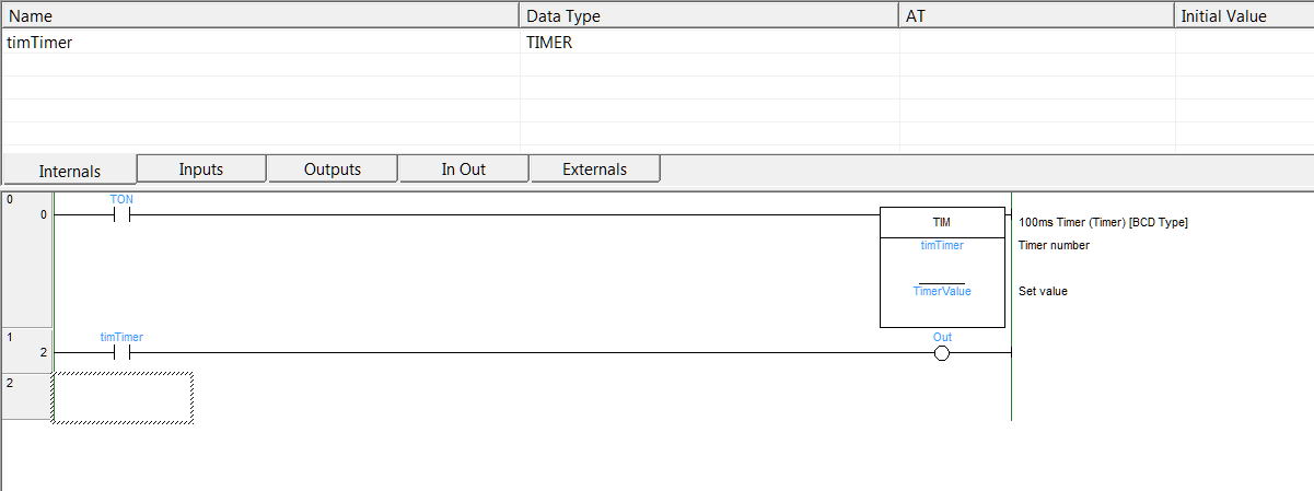
Create a variable with a function block reference of the Timer Ladder Function Block.
timerVariable(EN:= EN, TON:= condition, TimerValue:= number_or_variable, Out=>boolOutFlag);
//Regards
-
I'll post it when back to work, whenever that happens, I seem to have gotten sick.
-
Hi,
is it possible to pass a com-port from the computer to a simulated PLC-session in CX-Programmer? I can't get enough budget from my boss to buy a play-PLC for bus-experimenting, but I can buy a RS485 to RS232 adapter.
Since I can't emulate MODBUS messages, I'd like to connect to a physical network during simulation.
Edit:
Also, if anyone would be so kind: Would this be a sane way of implementing serial communication?
https://gist.github.com/RozeDoyanawa/0939f08db3fea6dc496a785403476364
//Kind regards.
-
Thank you.
After some searching I managed to make a workaround. The TIMERS.zip file referenced in the linked thread is not available to me, so had to figure out how to do it myself. :)
//Kind regards
-
Hello,
I'd like some help with using timers in structured text, how to make block independent timers like in Ladder function blocks in ST?
like IF condition THEN enabledTimerVar; END_IF; IF timerFired THEN doStuff; END_IF;
CX-Programmer says I cant use the TIMER datatype.
//Kind Regards.
-
We always use punch-tools at work, all from Greenlee. A hand-pumped hydraulic puncher is used to make the cutouts. It works well for 0-3 mm iron and 0-2 mm stainless. We have used them on 3mm stainless too, but that risks damaging the punches. And we figured that the 45x45 square punch we bought as a test works totally fine on 1.5 mm stainless and 2 mm iron with said hydraulic pump.
Something like this but with stainless punches: https://imgur.com/a/k5iNtGJ
-
Hi,
Dunno where else to ask, so I'll just vent my question here.
I've recently gotten into EPLAN and since there is like zero google results on anything regarding it, I'd be grateful to receive some help.1: I'm trying to put down some Siemens Sirius ACT command points onto the drawings, but I cant seem to link them... See. https://imgur.com/a/v03chzQ
2: Can I change the coloring of wires to match what the real wires is going to have? See. https://imgur.com/a/GVBxE4N Ref from ACAD E https://imgur.com/a/9SvQNwo
//Kind regards for any help in these issues.
-
Just an update to my own post, since I has now solved the issue.
Supplied is a PDF of the complete program if anyone else is looking for a solution to the same problem.
BusOccupied input should be used for multi-converter setups. Supposedly its externally setup to "join" all busy-outputs of these frequency converters with immediate update on both input and output. This is to ensure no two controls try to write/read at the same time.
Other inputs should be fairly self explanatory.
//Regards.
-
The machine I'm Sourcing the RPM from is not connected to the control network. So I have no "Master", hence follower is a bit out of the question.
VFD in question is a Danfoss FC51
Edit: But the current idea is to simply rely on the RPM to Frequency formula and hope that the result is close enough. -
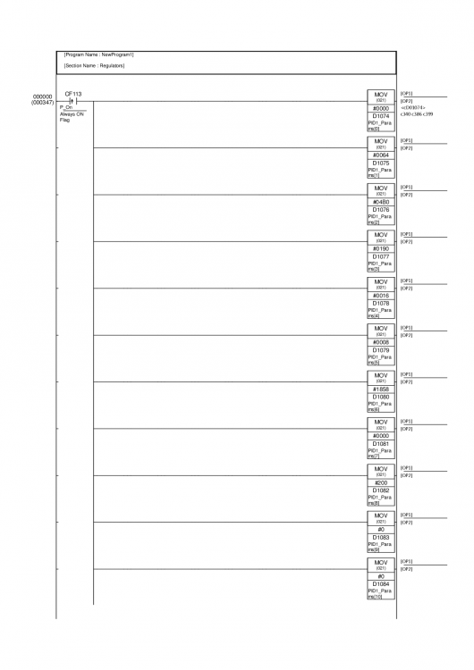
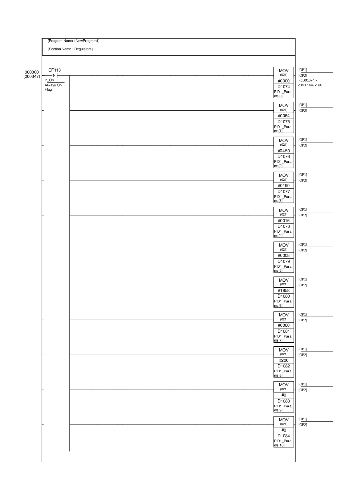
I found some relatively good working parameters... Tho I dunno why or how to tune them further... Also, Autotune fails horribly...
+1 P = #0500
+2 I = #0010
+3 D = #0010
+4 T = #0064
+5 = #000C
+6 = #1515
+7 = #0000
+8 = #2000
+9 = #0000
... = #0000
Any ideas on how to tune it?
Setpoint is RPM
Feedback is RPM
Output is a value 0-2000 hex corresponding to 0-100 Hz
RPM is roughly given by the formula RPM = Hz* (2 / poles) * 60, poles in this case being 4.
But lots of factors impact RPM, like load. Also, the Frequency Drive is slow to change, with internal ramp times, so its a bit hard for the PID to keep up
So, to maintain a certain rpm, the output needs to stay "on" at a given level +- a couple of 0.x hz.
//Kind regards for any feedback. -
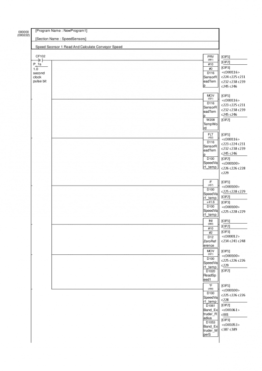
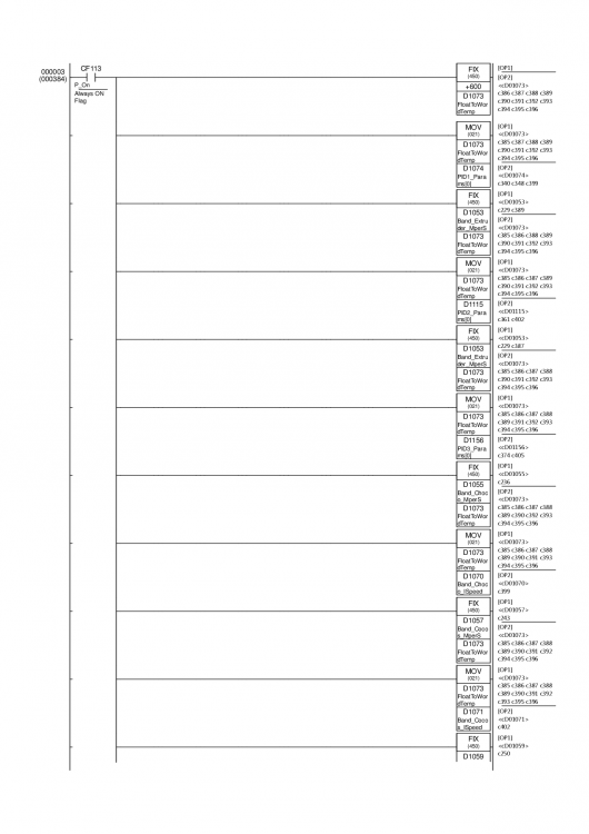
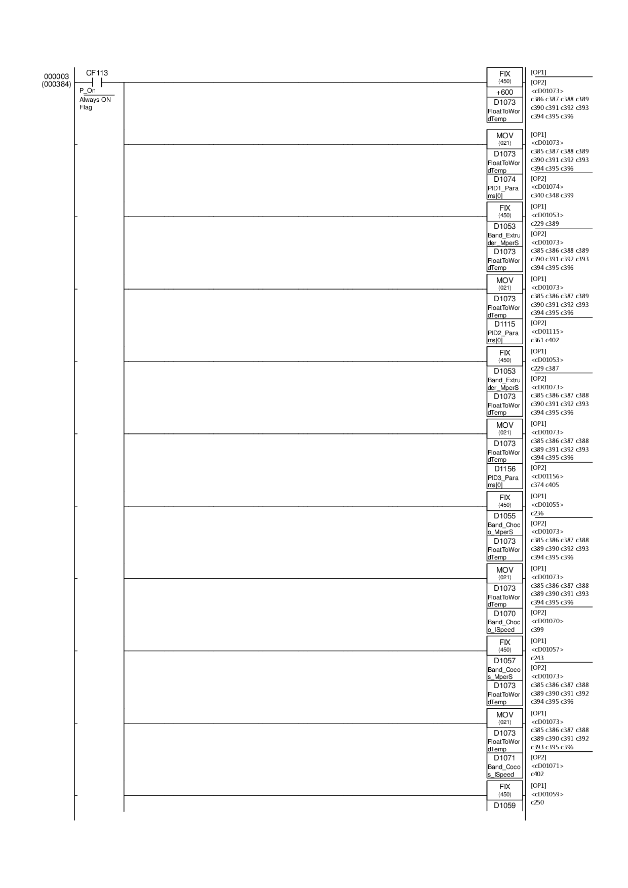
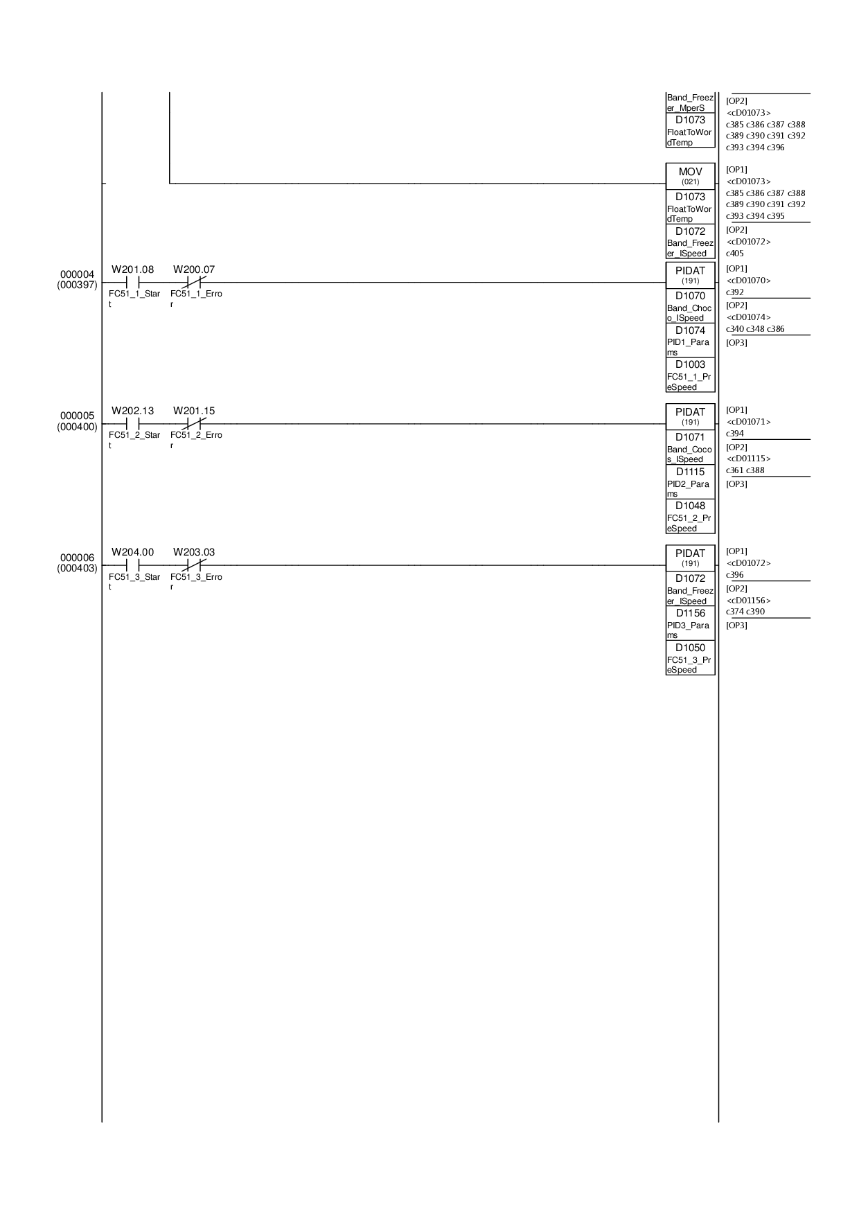
I have (currently) a program to convert the encoders pulses to rpm. m/s not in practice yet cause I dont have any belts connected to it, so a fixed 10-ratio is in place for that. But the RPM should be fairly correct.
I attach some picture prints of my program, both the sensor reading and regulator control.
And I did try autotune but the motor still goes on and off priodically and does not keep around a value.
//Kind regards.

-
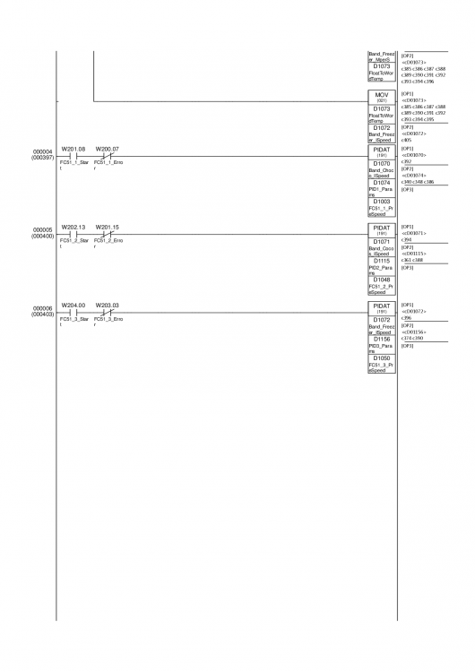
Hi,
I'm trying to create a regulator for keeping the speed of a motor match that of another. My feedback is pulses per second, converted to rpm or m/s. My output is an absolute frequency 0 to 1FFF (hex) representing 0-100% hertz.
How do I configure a PID or PIDAT block to regulate this? My attempts have all resulted in weird data or the MV being 0 to something far to low.
//Kind regards, me
-
Thank you for the links. I had missed the fact that its 3 words and then the message in bytes.... :P
In any case, here is my work in case anyone else wants it. VERY simple communications, no feedback or status checking.
https://anonfile.com/Z6pdU8c6b9/VFD_FC51.cxf
//Kind regards -
Hi,
I'm trying to build a very simple communications module for talking to a Danfoss FC51 Inverter, however, I'm stuck and is getting error on trying to change the speed...
Anyone familiar with how to use the Serial Comms that could help with how its done? Rewrite in ladder is OK too, I'm just not good enough to do this heavy things in ladder.
//Kind regards.(* Internal Vars: Modbus_CommandData_Port1 = WORD[50] @ D32200 TempHi = WORD TempLow = WORD Modbus_Port1_Executing_Bit = BOOL @ A641.00 Modbus_Port1_Executing_ErrorFlag = BOOL @ A641.02 Busy = BOOL Modbus_ReceiveData_Port1 = WORD[50] @ D32250 InternalStartState = BOOL InternalSpeed = REAL Inputs: EN = BOOL SlaveID = INT Speed = REAL Start = BOOL ErrorClear = BOOL Output: ENO = BOOL Done = BOOL Error = BOOL *) (* enum{ ReadCoils = 0x1; ReadHoldingRegisters = 0x3; WriteSingleCoil = 0x5; WriteSingleRegister = 0x6; WriteMultipleCoils = 0xF; WriteMultipleRegisters = 0x10; Diagnostics = 0xB; ReportSlaveID = 0x11; } //DiagnosticSubNumbers: enum{ RestartCommunications = 1; ReturnDiagnosticsRegister = 2; ClearCountersAndDigitalRegisters = 10; ReturnBusMessageCount = 11; ReturnBusCommunicationsCount = 12; ReturnBusExceptionErrorCount = 13; ReturnSlaveMessageCount = 14; } Coil 0 1 01 Preset reference LSB 02 Preset reference MSB 03 DC brake No DC brake 04 Coast stop No coast stop 05 Quick stop No quick stop 06 Freeze outp No freeze outp 07 Ramp stop Start 08 No function Reset 09 No jog Jog 10 Ramp 1 Ramp 2 11 Data not valid Data valid 12 Relay 1 off Relay 1 on 13 Not used Not used 14 Setup 1 Setup 2 15 Not used Not used 16 No reversing Reversing 33 Control not ready Control ready 34 Unit not ready Unit ready 35 Coasted Not coasted 36 Error, tripped 37 Error, no trip 38 Not used Not used 39 Error, trip locked 40 No warning Warning 41 Not on reference On reference 42 Hand mode Auto mode 43 Out of freq. range In frequency range 44 Not running Running 45 No res. brake fault Resistor brake fault 46 No voltage warning Voltage warning 47 Not in current limit Current limit 48 No thermal warning Thermal warning Register number Description 00001 – 00006 Reserved 00007 Last error code. See sectionException and Error Codes. 00008 Reserved 00009 Parameter index* 00100 – 00999 000 parameter group (parameters 001 through 099) 01000 – 01999 100 parameter group (parameters 100 through 199) 02000 – 02999 200 parameter group (parameters 200 through 299) 03000 – 03999 300 parameter group (parameters 300 through 399) 04000 – 04999 400 parameter group (parameters 400 through 499) … … 49000 – 49999 4900 parameter group (parameters 4900 through 4999) 50000 Input data: Frequency converter control word register (CTW). 50010 Input data: Bus reference register (REF). … … 50200 Output data: Frequency converter status word register (STW). 50210 Output data: Frequency converter main actual value register (MAV). *) IF EN THEN IF NOT Busy AND InternalSpeed <> Speed THEN InternalSpeed := Speed; Busy:= TRUE; Modbus_ReceiveData_Port1[4]:= INT_TO_WORD(0); Modbus_CommandData_Port1[0] := INT_TO_WORD(SlaveID); Modbus_CommandData_Port1[1] := INT_TO_WORD(16#0F); Modbus_CommandData_Port1[2] := INT_TO_WORD(16#00); Modbus_CommandData_Port1[3] := INT_TO_WORD(16#10); Modbus_CommandData_Port1[4] := INT_TO_WORD(16#00); Modbus_CommandData_Port1[5] := INT_TO_WORD(16#10); Modbus_CommandData_Port1[6] := INT_TO_WORD(16#02); TempHi:= INT_TO_WORD(REAL_TO_INT(InternalSpeed / INT_TO_REAL(256))); TempLo:= INT_TO_WORD(REAL_TO_INT(InternalSpeed - INT_TO_REAL(WORD_TO_INT(TempHi) * 256))); Modbus_CommandData_Port1[7] := TempHi; Modbus_CommandData_Port1[8] := TempHi; Modbus_Port1_Executing_Bit:= true; END_IF; IF NOT Busy AND InternalStartState <> Start THEN InternalStartState:= Start; Busy:= TRUE; Modbus_ReceiveData_Port1[4]:= INT_TO_WORD(0); Modbus_CommandData_Port1[0] := INT_TO_WORD(SlaveID); Modbus_CommandData_Port1[1] := INT_TO_WORD(16#05); Modbus_CommandData_Port1[2] := INT_TO_WORD(16#00); Modbus_CommandData_Port1[3] := INT_TO_WORD(16#07); IF(Start)THEN Modbus_CommandData_Port1[4] := INT_TO_WORD(16#FF); ELSE Modbus_CommandData_Port1[4] := INT_TO_WORD(16#00); END_IF; Modbus_CommandData_Port1[5] := INT_TO_WORD(16#00); Modbus_Port1_Executing_Bit:= true; END_IF; IF Modbus_Port1_Executing_ErrorFlag OR ( Busy AND Modbus_ReceiveData_Port1[2] <> 0) THEN Error:= TRUE; END_IF; IF Busy AND Modbus_ReceiveData_Port1[4] = 16#0004 THEN Done:= TRUE; Busy:= FALSE; END_IF; IF ErrorClear AND Error THEN Error:= false; END_IF; END_IF; -
Hi,
I'd like to ask if the following is compatible with Danfoss FC51 VFDs, and if not, for some kind soul to perhaps fix it. Or if there is any better way to approach communicating between a CP1L-M60 and a Danfoss FC-51 VFD. (RS 483 Modbus or FC).
https://www.myomron.com/index.php?action=kb&article=1475
//Kind regards


Help with TIA + S7-300 + IFM AC2504
in Siemens
Posted
Hi,
I recently scavenged a S7-300 from an old machine. The processor has a CP343-2P ASi interface module. Together with it came about 50 meters of ASi cable and eight IFM AC2504 (link below).
So, I have gotten a license for TIA Portal from my local school and is in the process of trying to figure out how to talk to the IO slaves. Wiring is complete. I have to wait for a programming cable to arrive in the mail, so I figured I could use the time to ask for help.
Do anyone have an example project using these type of devices? Or otherwise could offer help in how to talk to it. I really cant find much information at all online about how to use ASi and even less when it comes to third party ASi stuff.
//Kind regards.
IFM AC2504: https://www.ifm.com/se/en/product/AC2504