

Kiiza
MrPLC Member-
Content count
38 -
Joined
-
Last visited
Posts posted by Kiiza
-
-
The calculated result is just a DWord. The Dword has 4 bytes (2 words). When I check the DWord, I see all the 4 bytes contain information. And the information in the 4 bytes is not necessarily the same.
-
Thank you.
I will read the Easy Book and see what I can find in there.
The problem with converting from DWord to Byte is you lose the data contained in the other three Bytes. And you may not be sure if the correct information needed stays in the remaining Byte or is lost in the other three.
-
Hi pop29684,
Moving those figures into the bytes worked well. However, it worked for me when I knew what digit I wanted to display on the 7-segment. In instances where I can't be sure which digit will be displayed at a particular time, I am still struggling. The STL code I had shared earlier, I got help to convert it into SCL code and it worked. The only problem is it gives me a double word output but that is a lot more bits than I need since my display areas are only bytes. And I can't easily tell which byte to extract from the double word. If you may know another way, please advise.
Thank you.
-
Hello everyone.
I am looking for a link to download Microwin 4.0 sp7 or higher and not the update. Kindly advise me.
Thank you.
-
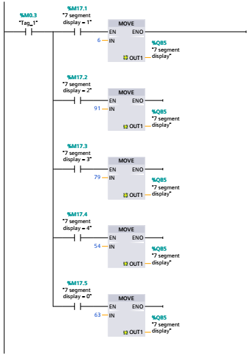
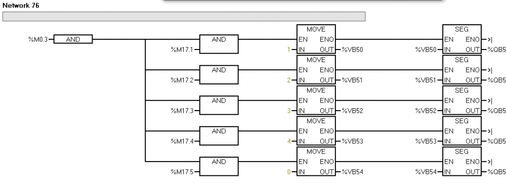
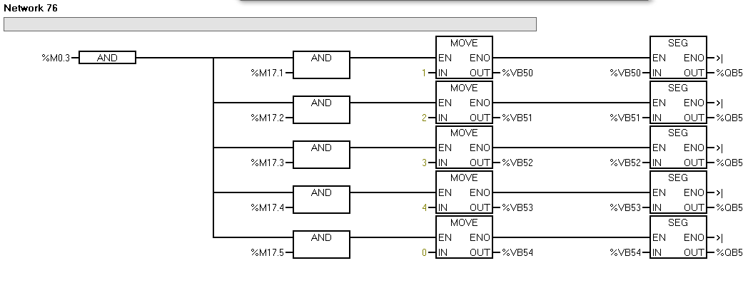
On 6/17/2019 at 0:59 AM, pop29684 said:Analysis: the integer value stored in VB50 (decimal "1") is sent to the 7-segment display (QB5) when bits M0.3 AND M17.1 are both true (high, ON, 1). The 7-segment display must see segments b and c both equal 1; all other segments must equal 0.
The S7-200 manual (p325) shows the relationship between the integer value to be displayed and the corresponding segments that must be ON for the correct value to be seen on the 7-segment display. The 7 segments are ordered from "a" to "-", with segment "a" being the LSB of the byte and "-" being the MSB of the byte.
In the network example you provided, only integers 1, 2, 3, 4, and 0 are displayed on the 7-segment display. These integer values can be directly converted to a decimal value that will turn on the corresponding segments of the 7-segment display. The resulting code is shown below. It is a direct replacement of your network 76 without inventing a module to act as the "SEG" instruction. Nice, quick, simple, and easy. Just what the doctor ordered! :)
Edit 18 June 2019: The absence of the "SEG" instruction for the 12## series CPUs is not due to the TIA Portal programming software. Rather it is because of the CPU (hardware) you are working with. The "SEG" instruction is available in TIA Portal when working with 15## and 3## series CPUs. I suspect the instruction is also available for the 4## series CPUs but I cannot confirm this because I don't have any current projects in TIA Portal that use this series of hardware. The TIA Portal software only allows access to instructions compatible with the hardware you are programming.
This is really easy and very helpful.
Thank you very much.
-
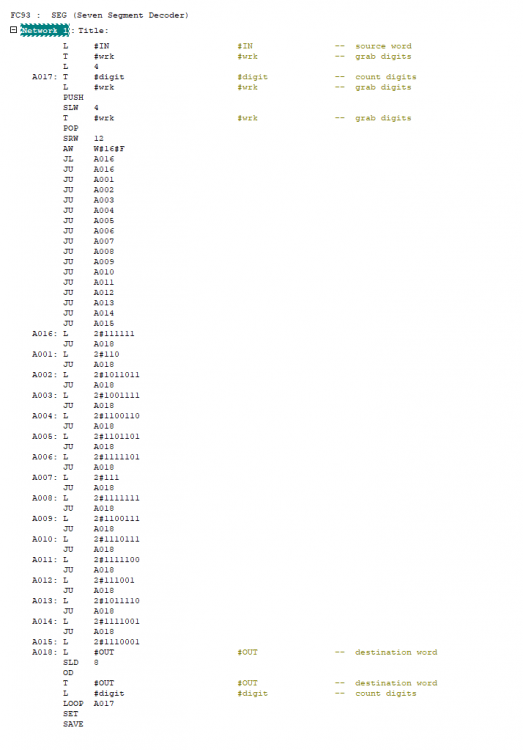
Hi guys,
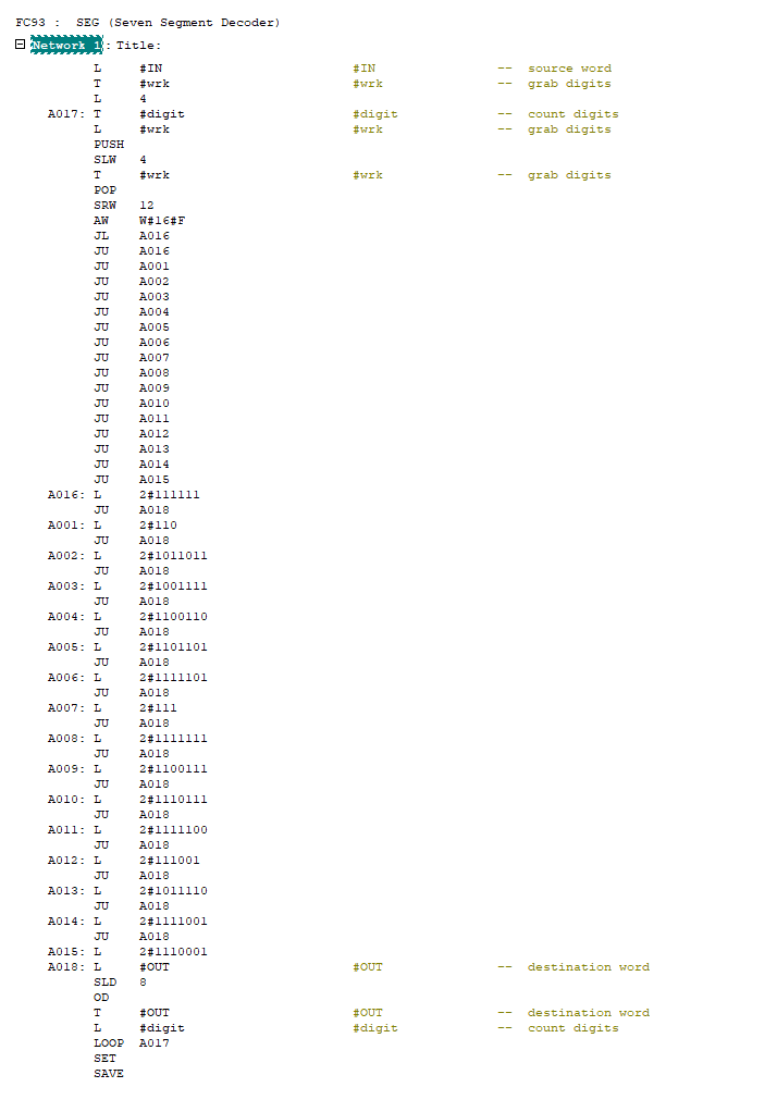
I managed to get the instruction in STL; I have attached it in the Screenshot down. However, now the challenge is, I need to implement it in SCL since the later versions of TIA do not support STL any more. If any one knows SCL and may help us to convert it, it would help us a lot.
Thank you.
-
Hello guys.
We are trying to replace a S7 200 PLC at our station with S7 1200. We are reading the program on the S7 200 and recreating the same on the S7 1200. However, we have encountered the SEG instruction used several times in the S7 200 (microwin) program. And the SEG instruction is not available in TIA Portal (we are using TIA 11) for the S7 1200. We have tried to read the s7 200 system manual but the explanation of the instruction is not sufficient to help recreate it.
Could anyone know how we can create our own equivalent of the SEG instruction?
If anyone has the SEG instruction already created as a program, it would be very helpful.
Thank you.
-
Hello IO_Rack.
Thank you for your reply. I do not know the comm settings of the NS. I could not find a way to read the IP address of the NS. I will try again to autodetect the NS Ip addrees and follow the two timeout sequence and hope that's the catch.
Thank you.
Kiiza.
-
Hello Forum,
We have a NS15-TX01B-V2 at our Plant in Uganda which we are using with a CJ2M PLC. We want to take backup from the PT to PC using Ethernet but we have not succeeded yet. We have consulted the manuals but they are not very elaborate. Someone here may know the step-by-step procedure we can follow. to achieve our goal. We shall be very grateful.
Thank you. -
I will try that out. Thank you very much.
-
Hello guys, hope you are well.
I have with me KOYO PLC C0-02DD1-D. I have programmed it successfully. However, I do have a challenge with it's digital outputs. I expect a voltage of 24Vdc from the outputs but I am instead getting a voltage of 12Vdc. Even the 12Vdc I measure at the outputs looks fake voltage because whein I use it to energize 12Vdc relays, they don't get energized. I appreciate your help.
Thank you very much.
-
On 1/22/2018 at 11:21 PM, BobB said:I believe you can get it here.
or here
http://www2.omron.com/l/22312/2017-05-30/62qtz6
not sure which version is is though.
I downloaded v4.27 but for some reason it can not install. Anyone who knows if I have to follow a particular procedure?
-
Hello guys,
I am looking for Cx-One trial version and I am interested in version 9.4. Does anyone have a link where I can download a copy from?
Thanks in advance.
-
Now I understand.
Thank you very much.
-
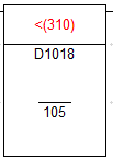
I have attached two Pictures. In the first picture (OMRON), everything is OK. In the second picture (OMRON2), the instruction remains red because I was trying to compare direct with a value of 105. Does OMRON not allow that?
-
Hello guys,
I need help. I have an OMRON PLC; CJ2M series which I am not very familiar with. I need to do comparisons, but I see that do that I can't just compare with a value. It looks to me that I have to store the value I need to use to compare in a memory address and reference to the memory address for my comparison.
Is it possible for me to compare using a value and not have to first go through a memory address?
Is there a way to use the instruction to store the value in a memory location ?
Or do I specifically have to use CX-Designer for me to wrote the value to a memory location?
Thanks in advance.
-
Thank you very much for that information. I will call ABB and hope I have some luck with them
-
Hello guys,
I hope everyone of you has started 2017 well.
I don't have any experience with ABB PLCs but soon I have a project with an ABB PLC and the software Automation builder version 1.2. I ma looking for documentation that will help me get started with the programming basics of this software from scratch. If anyone knows where I can get such documentation, I highly appreciate because I can't seem to get any when I search on the internet.
Thank you guys, and Happy new year everybody.
-
Thank you Dick Oestreich,
That does give me a general understanding.
I am used to SIEMENS PLCs and I would relate the two as follows from what I seem to understand;
D..........................Data block memory
W.........................Local memory
H..........................The M memory
Correct me if I am wrong, Thanks again.
-
Hello guys,
I have gotten to a level where I can do a few things with an OMRON PLC. However, there's something that is supposed to be basic by now but I still don't understand it, and I will appreciate your help on this .
What is the difference between the D, W and H memory areas of the PLC? And in what instances do I utilise each of them for storage of my data?
Thank you.
-
Thank you Michael
-
I see, I'll do whatever calculations I need to do before the conversions.
Could you be having an example of a project where you've used the PID instruction? It would be of great service to me.
Thank you.
-
That's a little bit crazy. Because when conversions are done from real to integer then you are either truncating or rounding off which obviously affects the accuracy.
-
Thanks, I was wondering how I was supposed to do that.
The next question now is; There are bunches of bits from words that are used in islolation for instance Bits 04 to 15 of C+5 are supposed to be for 2-PID parameter (a). There are other separate bunches of bits. How do I manage to write to only that stream of bits and not the rest of the bits within that word?
If anyone has an example of a project where they have used this, it would be of very great help.
And the additional question is; do I always have to move the data as word? Because I realize sometimes I need to write floating point values and those would typically need 32-bit address areas, I don't know how that affects the C, C+1, C+2,... addressing order.
Thank you.
S7 200 SEG INSTRUCTION
in Siemens
Posted
Thank you. You have been very helpful.