

Andrei Blagaila
MrPLC Member-
Content count
225 -
Joined
-
Last visited
Posts posted by Andrei Blagaila
-
-
If I use at the begging of a POU the MC Nn Mn command do I have to use something at the end of the POU? I want the entire block to work only if certain conditions are True.
Thank you
-
Hi guys,
I'm playing around with a PT100 temperature reading module (AJ65SBT2B-64RD3 ) and I came across something strange. I took the example program written in the manual and copied it exactly. It works but now I figured that some of it is not needed maybe and some is not clear what it is used for. Can someone explain what exactly do these two values are in the settings? I'm using all 4CH of the module so maybe I need to change something or I can just delete it if it's useless in my application. (I read the temperature in a room and turn on or off a IR Lamp depending on that temperature).
Thanks,
Andrei
-
How come?
-
Now I know not to trust the simulator. I really thought I had a setting wrong or something.
-
This is helpful to read. I want to Write on the PLC automatically using a batch file. You put the SW in a certain folder. Put the PLC in STOP and run the batch file. It copies them automatically. I don't think this can be done so I got the ideea of using the CF card. But I keep getting asked if the batch file is possible.
-
Perfect. So I need to put from Reserved Station to No Setting 28/30 and 30/32 for Stations 30 and 32. Very well explained. Thank you so much :D
-
I have an already configured CC Link network. My question is: Which of the attached is node 32? (I did a modification that implies that I should change the settings for it). Is it 30/32 or 32/34? I'm not sure how it works. It's an analog PT100 reading module. I also want to add node 30 with 16Di+16DTO. Can someone explain why it's written 30/32? It's confusing when you're coming from another PLC brand.
Thanks

-
I found the problem if you are interested. I used a PLS command for the memory bit trigger. It was too fast. Created a delay of 1 second and it works.
1 person likes this -
Hi guys,
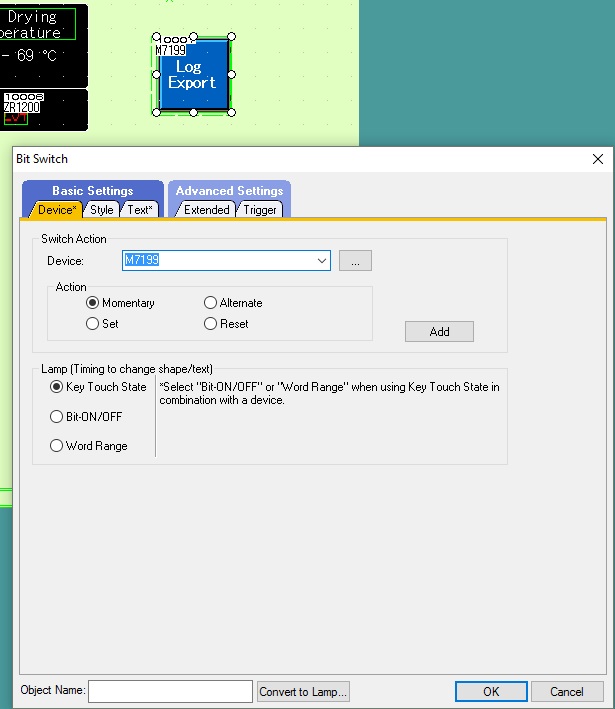
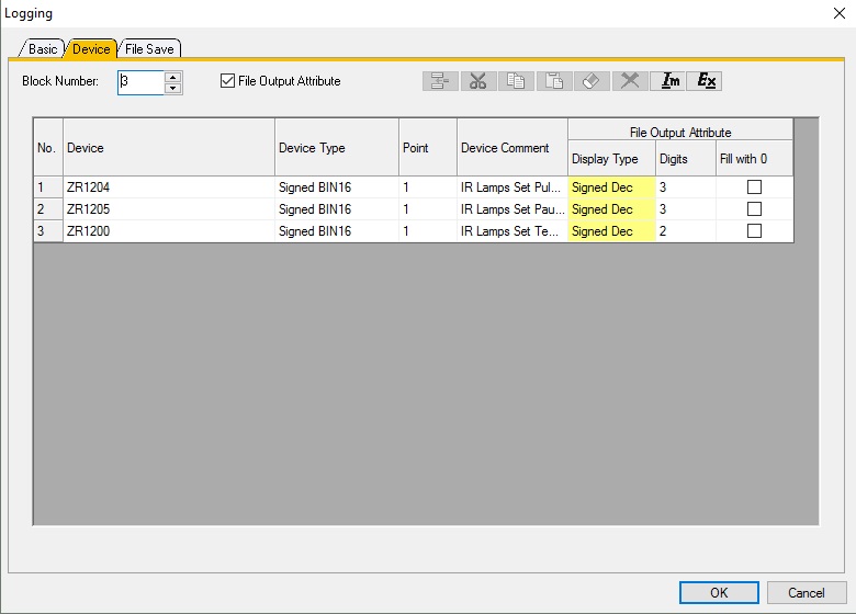
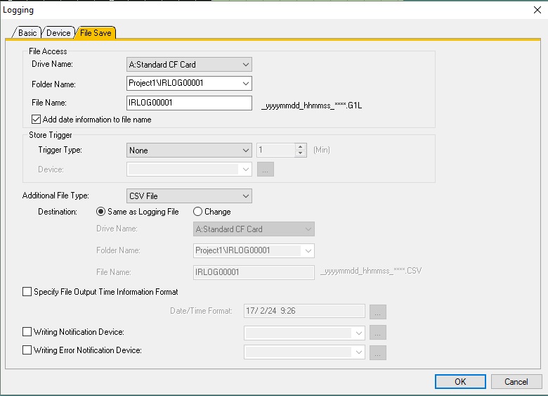
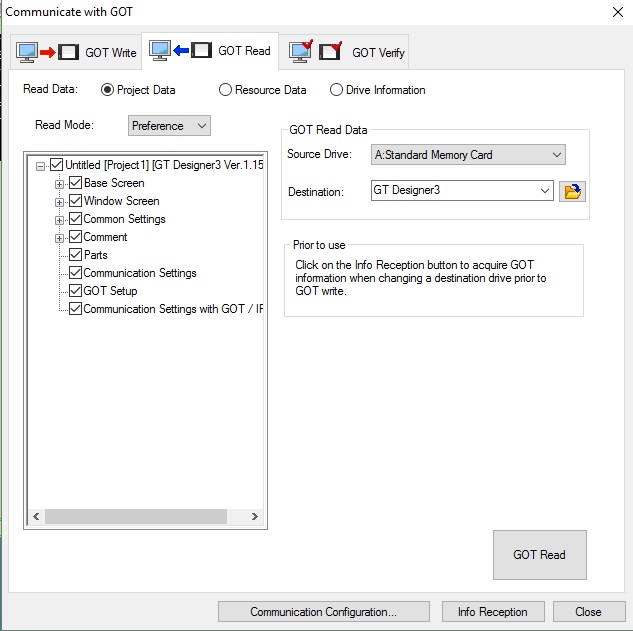
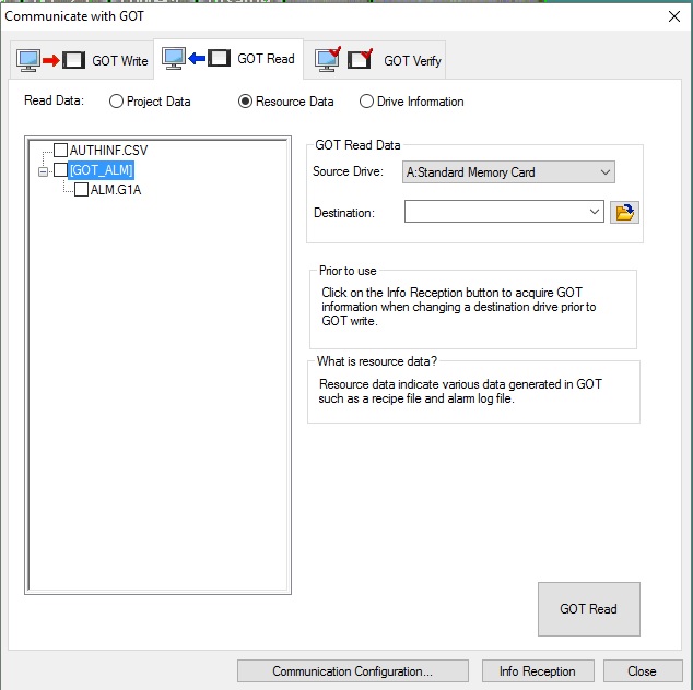
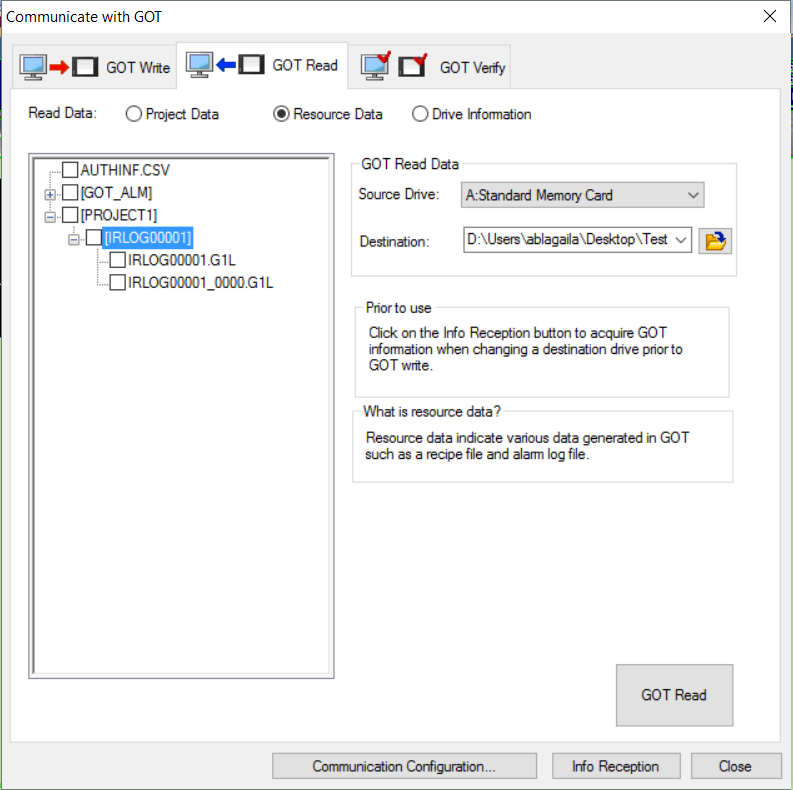
Yesterday I posted a question about how to create a trigger for a log. Now I have the next problem. I created my log, loaded the Logging firmware on the GOT but the CVS file is not generated. Can someone tell me what i'm doing wrong? I am attaching all the settings and the PLC part of the program. I want the values of ZR1200 ZR1204 and ZR1205 every time they change. They are recipe values. I tried also putting a button to create the log file on the HMI. Did not work.


-
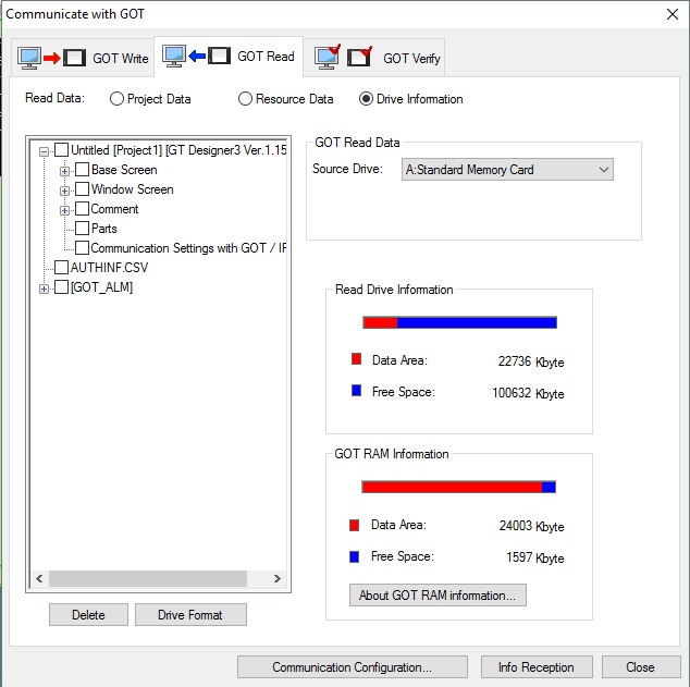
It works but I don't know how to see what's on the CF card to see the log. Do you know how to access it by USB or something? Or only removing it and connecting it to a Card adapter?
-
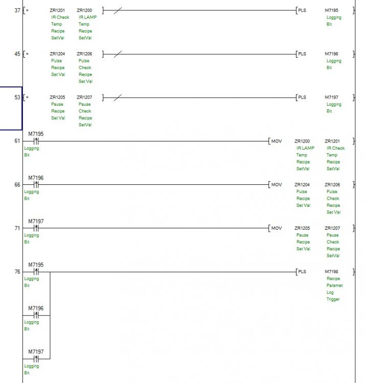
Sadly no :( I would have solved by now if so. I have a simple ladder project that I need to add on to. I changed the program a bit and now it pulses 3 bits that i will put in paralel to a bit used as a trigger
-
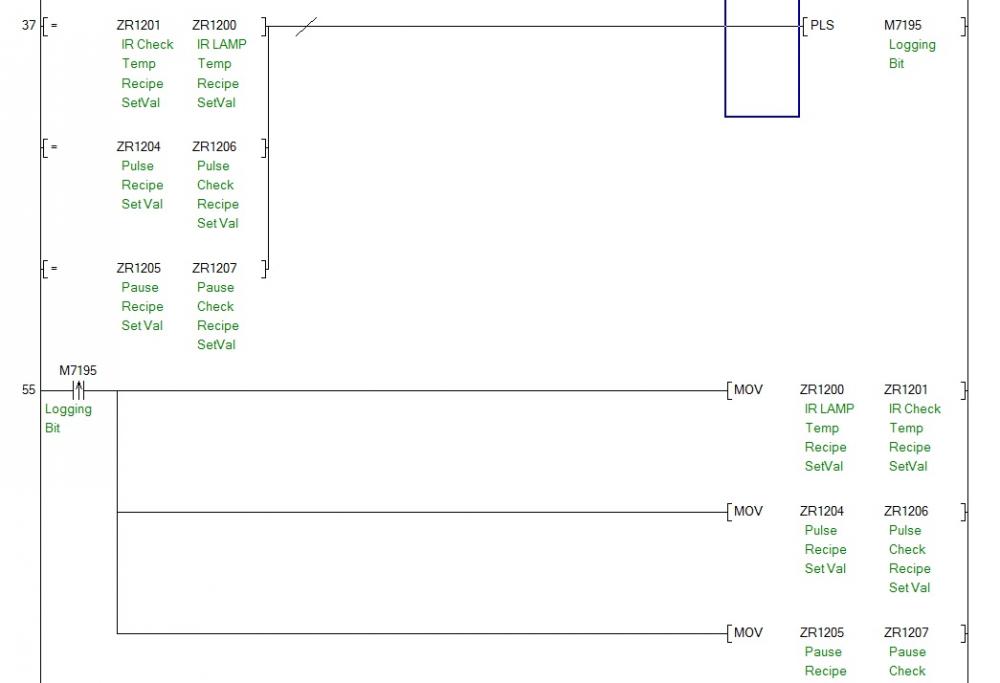
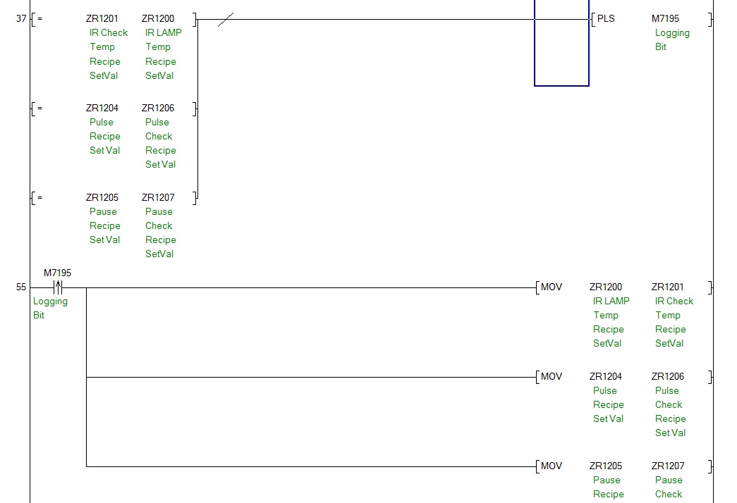
Something like this seems to do the trick. It compares the value used in a recipe with another register that is used to store it just for this. If not it triggers M7195 that is called in the GOT LOG as a trigger to LOG. Hopefully it will work and log ZR1200 ZR1204 and ZR1205
-
But once it boots up from the card and the CPU has a battery is it moved from the card to the internal memory?
-
It helps a bit but I use ladder diagram. From this I need to adapt to see because I don't have an else command in ladder.
-
Actually I found options in GT Designer to do the log. I need just a trigger. I want that trigger to be the value change of ZR1200 but i'm having trouble conceiving 2 lines of software that pulse a bit when ZR1200 changes values. Any suggestions?
-
Hi guys,
Have any of you tried to create a log file to store each time the value of a ZR register (recipe parameter) has been changed and the old and new values? I want to create a log that exports to a file on the CF of the HMI maybe.
Thanks,
Andrei
-
So without using GX Works it cannot be done. I talked to my mitsubishi rep and he suggested I put the SW on a CF card and when I put the CF card in the Q50UDEH it automatically copies the SW to it if the CPU is empty. Have you tried this?
-
I have two. That's not a problem. The problem is everything is programmed in Simple Ladder and was done by another person. Now I have to modify certain things and it's a pain in the *** untill I figure out how they did things and why.
1 person likes this -
On the HMI and PLC it's working fine. On the Simulator for some reason it moves in a faster pace. I thing because it uses the CPU of the PC to run everything. Strange!
-
I Am sure that the timer is not used in another place. The ZR is used for another timer but It's value is set in the HMI only.
I used SM410 and it does not show me any value in T150. It may be too short for the simulator to register.
I will try to load it on the PLC rack and try it there. Maybe something changes.
-
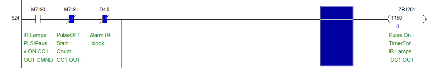
I loaded the ZR1204 with the value 100. With my phone I timed it and it was around 4-5 seconds.
I changed ZR1204 with K100 and timed that as well. It's slower 6-7 seconds. I really don't understand it.
-
None of the two. I used as bellow.

-
I found the page. But a question. How do I tell the software which is a high speed timer and a low speed timer? I have 100ms set at a low speed timer and 10ms at high speed timer. I use a timer T for a recipe value that goes up to ZR1200 (the recipe registered value). If I put 10 it's one second. But I I put 100 it's not 10 seconds. It's shorter. Why?
-
Hi guys,
I'm using a Q50UDEH cpu and I need to add some timers. Can someone explain in seconds if I put a timer like T1 K1, K1 is 0,1 seconds or 0,01 seconds?
Thanks

MC Function on Q CPU
in Mitsubishi
Posted
Sure. I have a function for the machine that I want to abilitate and disabilitate. If the conditions are true is works, if not it skips the code. I tried with GOEND but if by accident the Latch is switched off while working the outputs freeze ON and it could cause major problems.