

JZerb
MrPLC Member-
Content count
31 -
Joined
-
Last visited
Posts posted by JZerb
-
-
That i understand, what Im foggy on is the use of # in front of a MOV or COP command within the logic in question. It was my understanding that in order for the # to mean anything of significance within the logic that the S:24 Status register would need to have a number in it, not just a 0. I guess what Im trying to say is that to me it seems as if this logic has indexed addressing setup improperly, because in this instance it seems as if its not setup at all.
-
I know this is an old thread of mine but im hoping bumping it gets the answer instead of starting a new.
if you have Indexed Addressing being used in a program, for example i see COP and MOV commands with #N or #ST used as sources and destinations. But when looking at S:24 and seeing 0's for the entire word, what would be the reasoning behind using the # for indexed addressing in the first place since from what Ive read and understand there needs to be an actual value in the Index Register S:24 for it to actually do something.
-
On a Panelview Plus 600 i have done this if it has a usb port. You can put this on a USB stick and it should take the .mer file thats on the panel and copy it to the USB for you as soon as you plug it into the panel. If you dont have a USB port this can be done with a flash storage card i believe too. just change the last part of the code that says \USB Storage\ to \Storage Card 2\ ( i THINK its storage card 2, it may be storage card 1 youd have to try it out and see what happens)
write this code in notepad. save as autrun.bat then transfer that onto a USB stick. 4gb or less, FAT16 format so the PVP recognizes it.
copy "\Application Data\Rockwell Software\RSViewME\Runtime\*.mer" "\USB Storage\"
pausewhen inserted into the panelview the windows ce command line editor will pop and and it will say if the process described above executed properly or not, itll say hit any key to continue at the bottom of the text on screen, upper right hand corner there is an X to close that screen, tap that and youre all done.
1 person likes this -
Good idea. I didn't think of that situation. That setup may be easier then the animation Route within FTVS. And I was planning on saving whatever file format was actually the smallest KB wise. Whether it was a bmp png or jpeg.
-
Since I'm still very new to this, only about 6 months in, I appreciate the feedback about keeping the display "clean". I certainly agree and I'm only looking to spruce things up a little bit here nothing too major. It seems like you PC are doing the same thing that I am looking to do, since the HMIs I program are also used for machines.
Now if I wanted to show a machine in a different state, for example say a lift with a platform that goes from ground level up to a mezzanine, would I be making three or four different drawings in Illustrator with the machine in different states? Or would the proper way to do that be using one picture and then moving it to different positions on the HMI screen using the Animation function in FTVS?
-
Would like to spruce up some screens I've been handed that currently just have colored boxes with text in them. Plan was to take the .dxf files from the engineering drawings, import into Adobe Illustrator, edit, then export from there as a .bmp for use in FTVS. Questions are, first off, is that the best way to do what I'm looking to do? When I import the .bmp file into FTVS should I be putting it into the Images library? Or should I create my own library with custom images in Symbol Factory?
-
awesome, thanks! ill have to read up in that pdf this evening and see if i can get my head around what youre saying.
-
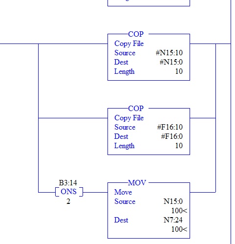
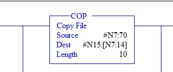
trying to understand, so that i may modify, a section of logic here and ive come across something i have yet to see in my limited time programming. the COPY commands here with a # and also a [ ] around the integers is what is confusing me. from what ive read you need to use the # sign in front of a string integer in order to use the COPY command? any sort of light shed on ths subject would be greatly appreciated.
-
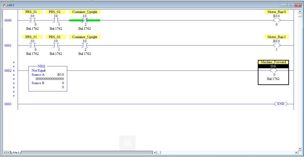
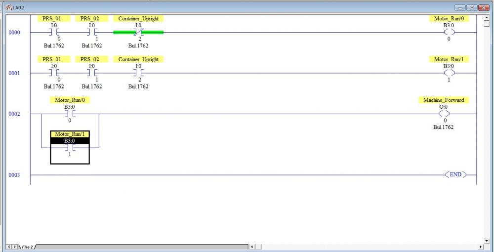
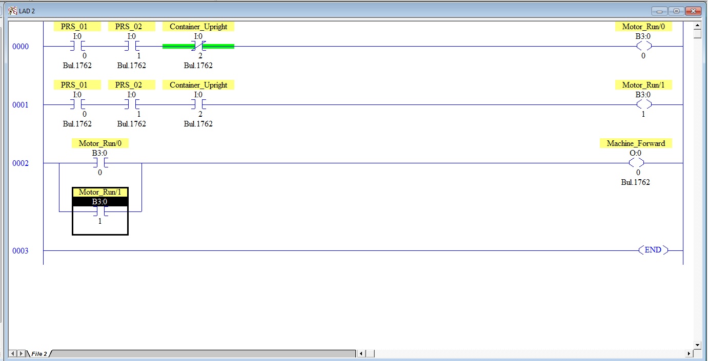
dragging this one up from a few months ago, laid out two sample ladders and was curious as to which way was the more 'proper' way to get it done.
in the make believe scenario the machine is picking something up and flipping it over and then continuing to lift the piece that it has flipped over up into the air. should i write the ladder so that the OTE for the Machine Forward is just triggered by either of the OTE B3 bits that you see on the first two rungs? or should the OTE for Machine Forward be triggered by something like a NEQ function that would be looking at the entire B3:0 word, and this i could just continue to write rungs that were for different machine conditions that could be met but would all still allow the end result of the motor running and thus the machine going forward.
-
The firmware is greater then that yes, it's a brand new unit but I did check just to make sure the other day that it was.
I will try it with the spacing Monday at work and see what happens.
-
I have the name whited out in paint. The company name is there before the underscore. So it reads companyname_screen_saver.bmp
-
i wanted to change the little bouncy AB logo that comes stock on the panelview 600's to a company logo and in my searching on how to do so i found this on the web and tried to do it today and had no luck. i attached below the error message that im getting when i attempt to do this. looking for some advice as to what i may be doing wrong. when i plug the USB stick into the panelview the error i get is File Not Found, as apposed to the screenshot i attached where i have the USB stick plugged into my laptop. i have the autorun .bat file on the main directory of the usb stick as well as the .bmp file that im attempting to load as the screensaver.
28335 - Changing the Screen Saver Bitmap on PanelView Plus and VersaView CE
Changing the Screen Saver Bitmap on PanelView Plus and VersaView CE
Introduction
A bitmap image may be displayed when the screen saver activates. This image is randomly moved around the screen. By default the terminals have a bitmap named ssfloat.bmp which is used as the screen saver image.
This technical note describes how to change the screen saver image on the following terminals:- PanelView Plus 400 - 1500 with Windows CE.NET 4.1
- VersaView CE 700 - 1500 with Windows CE.NET 4.1
Note: Previous terminals running an earlier version of Windows CE do
nothave the screen saver
imagefeature (e.g. PV+/VVCE with Windows CE 3.0). On these terminals, when the screen saver is activated, the display back light was simply turned off.
It is not possible to change the screen saver on PanelView Plus 400/600 prior to V3.20.08 firmware.
From 3.20.08 release notes:
PVP400-600, Removed the "system", "hidden" attributes from the
file ssfloat.bmp so that the customer can replace it when it is in the
\windows directory.Back light Intensity and Screen Saver
For the screen saver bitmap image to be visible, the backlight intensity must be set above 0%. To change the backlight intensity of the PanelView Plus, go to "Terminal Settings" through the main configuration screen. Select "Display" and press enter. Select "Screen Saver." Change the backlight intensity using the arrow buttons.
To change the backlight intensity of the VersaView CE, follow the directions for the PanelView Plus, or open the "display" icon under Start-->Settings-->Control Panel. Click on the screen saver tab and change the backlight intensity.
Format of the Bitmap- The bitmap can be of any complexity and size. However, a very complex bitmap will use more memory. Also, a bitmap that has a large resolution may either not fit on the screen or will not float around on the screen correctly and will appear sluggish. Therefore, it is suggested that the bitmap be as simple as possible and small compared to the screen size of the unit. Those screen resolutions are as follows:
PV+/VVCE Resolution 400/600 320 x 200 700/1000 640 x 480 1250 800 x 600 1500 1024 x 768 The lower left pixel of the bitmap is used for transparency. When the bitmap appears on the screen, any part of it that matches the lower left pixel will be transparent (i.e. if the lower pixel is black, anything black on the rest of the bitmap will not be visible on the screen).
If a portion of the bitmap is not appearing correctly, the pixel will need to be changed. This can be done on a computer that has Microsoft Paint installed on it. Once the bitmap is opened in Paint, zoom in to the lower left area (approximately 800%), and change the color using Paint tools.
Changing the Default Screen Saver Bitmap to a Custom Bitmap
Create a file on a desktop or laptop computer named autorun.bat. In the file place the following three lines (place the name of the custom bitmap in the place of "oem.bmp"):
copy \"Storage Card2"\oem.bmp \Windows\ssfloat.bmp
copy \"Storage Card2"\oem.bmp \"Storage Card"\Windows\ssfloat.bmp
pause
Place the file autorun.bat on a Compact Flash card and insert it into the external slot on the terminal. The autorun.bat file will automatically be run. Make sure the files are copied correctly by observing the Copied 1 file(s) messages. After completed, close the window by pressing a key or tapping on the X in the upper right.
If using a USB memory stick instead of a Compact Flash card, replace the term "Storage Card2" with "USB Storage" in the batch file. The autorun.bat will not fire on insertion of the USB. Cycle power with the USB storage device in the slot to fire the autorun.bat.
For PV+ 400 and 600 units, it is necessary to reset the terminal in order for the bitmap to be loaded into memory properly.
Return to the Default Screen Saver Bitmap
Create a file on a desktop or laptop computer named autorun.bat. In the file place the following two lines:
del \Windows\ssfloat.bmp
del \"Storage Card"\Windows\ssfloat.bmp
pause
Place the file autorun.bat on a Compact Flash card and insert it into the external slot on the terminal. The autorun.bat file will automatically be run. After completed, close the window by pressing a key or tapping on the X in the upper right.
For PV+ 400 and 600 units, it is necessary to reset the terminal in order for the bitmap to be erased from memory properly.
Alternate Method on VersaView CE Terminals
Another way to change the screen saver bitmap on the VersaView CE is to use the Control Panel. Go to Start-->Settings-->Control Panel and double click the Display icon. Click on the Screen Saver tab, then click on Browse, near the bottom of the window. Use the explorer window to browse to the location of the new bitmap (for example, the compact flash card would be under "Storage Card 2." Select the bitmap and press open. Make sure that the backlight intensity is set to a value greater than 0. Click OK.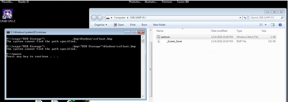 1 person likes this
 -
i assume my dongle driver is correct/working because it does activate the software and allow me to re up the grace period with Logix.
-
did that when i got into work this morning and all loaded up just fine, thanks! i wonder what the grace period for FT is now. Sucks its not the 7 days like Logix is.
-
trying to open up a project in FT view studio that i had opened up just the other day and its now giving me an error that reads....
The HMI server in area 'project name' refused to load its project. The HMI server is not licensed and cannot open a project with more than 5 displays"
I have a USB dongle that i use to activate my software once every few days, and RSLogix 500 will work for up to 7 days once the dongle is removed from my laptop. Just the other day i had this file opened in FT view studio and was able to view it just fine, the dongle was no attached to my laptop at the time. hopefully someone can shed some light on this issue for me, thank you.
-
Thank you for taking the time and explaining some of this stuff to me, it's very much appreciated.
-
I PM'ed it to you. Thanks!
-
This is exactly how the program I modified is written. The bit flags are, for example, B3:1/0-B3:1/15, and there are OTEs that are controlled by checking to see if all of the bits in that word are set to 0. My issue was I couldn't figure out how to name the word. I wanted to add another one for another function we were adding into the program and I couldn't quite figure out why it wouldn't let me name the entire word like it was with the exsisting program. Which say said Invert_Fwd for the word at the bit address I said above, and then each bit within that word was labeled accordingly. Invert_Fwd/0, 1,2, etc
-
Thank you for taking the time and explaining this to me. The pictures are even more helpful then just words! I'm pretty sure like I said above I tried to use a timer that when I opened Timers data file seemed that it didn't have a name to it under symbol so I figured it wasn't used. I'll have to look again at work Monday now that you've shown me where to properly look and see if it was indeed used and just not labeled, or if there is another issue.
Dont want to push my luck here and ask to much but another issue I was having the other day was that under the Binary bits data file I wasn't able to name a word. So that say any of the 16 bits that were in that word could be looked at all at once within the ladder and if they weren't all true or false then an output would or would not turn on. If that doesn't make sense I can try and post screencaps like you did above for clarity.
-
2 hours ago, Joe E. said:If the timer register is used in another place, it will not work properly. IOW, if you're using T4:10 as a TON in one part of the program and then add an RTO (or another TON or a TOF) elsewhere that's also using T4:10, it will not work correctly if both timer instructions are being scanned at the same time.
Do you have a free register in the timer file?
I thought that the register was free when I looked in the Timers bin file, but perhaps it was used somewhere and just didn't have a description name added to it so I thought it was free. But as I was browsing through the program today I noticed a timer on a rung that had not been deleted from the previous rendition of this program from another piece of equipment. I'm pretty sure that was what was messing me up, but I figured out another way around it regardless. I have the old program still and I'll look at that tomorrow. If it's still an issue I'll post that file to see what I'm missing in regards to making it work properly.
-
Was modifying an exsisting program today and wanted to add in an RTO timer to an used spot in the Timers file. I set the ladder up and loaded it into the PLC but the timer would never start to accumulate. As soon as the program started it would just set the DN bit for the timer and that would be that. I then just set an RTO to an exsisting timer within the file that used to be used for something else that's no longer applicable and everything worked out fine. Am I missing something?
-
Awesome. I hope to get this setup in the next week or so and like I said above, I'll post back with the results. I figured what you just said above, since the activation is tied to the USB dongle. Cloning the hard drive shouldn't cause an issue.
-
Thank you both for your answers. I will give this a go in the next week or so and report back here so others who may have the same question will know the outcome.
-
I forgot to mention that the license I use is shared with another computer at work already via one of ABs activation dongles. If I put that in the original post would you have given me the same answer above?


FT View ME Datalog
in Allen Bradley / Rockwell Automation
Posted
If multiple Datalogs are needed why not run DataStore plus ActiveX on the HMI?