

Qasem
MrPLC Member-
Content count
29 -
Joined
-
Last visited
Posts posted by Qasem
-
-
The program was originally installed on a panelview 1000 . Now all work is converted to *.med to work on. PC.
What is interesting here is that the some tags are missing and some other tags are not supported.
Could this be the problem!
-
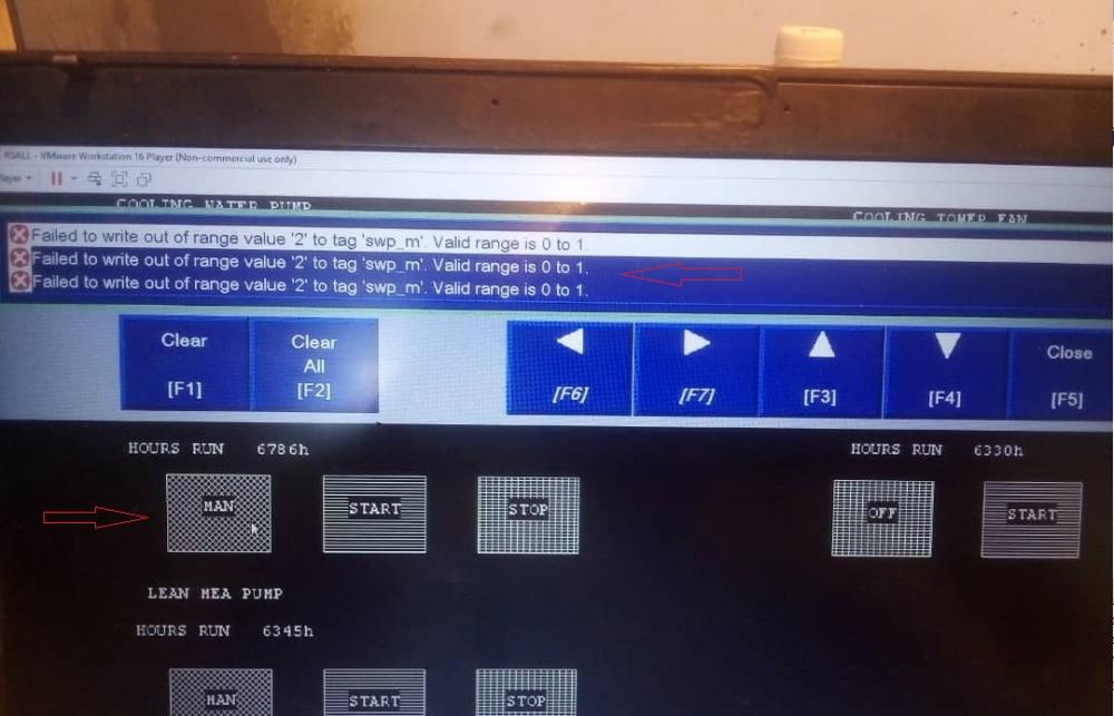
2 hours ago, alan_505 said:It looks like you are trying to write 2 to a digital (bool) tag, which you can only write a 0 or a 1 to.
The tag that you are writing to needs to be an INT or a DINT, not a BOOL.
Yes you are saying right but this program and code was written by someone else and it happened that the PLC accept this and the pump can be either OFF/MNUAL/AUTO
I know it may sound odd but this is it
-
Hi,
I have an HMI program which write a value to the PLC to decide the mode of pump control there are 3 options : OFF / MANUAL / AUTO However the program returns a failure massage as seen in the attached photo
What should we do?
-
5 hours ago, BobLfoot said:Did you look at the Rockwell OEM list I posted in your other topic?
Yes I did but the list did not help
-
Hi,
I am looking for Allen Bradley spare parts, Who can recommend me a good source in the UK or elsewhere in europe?
-
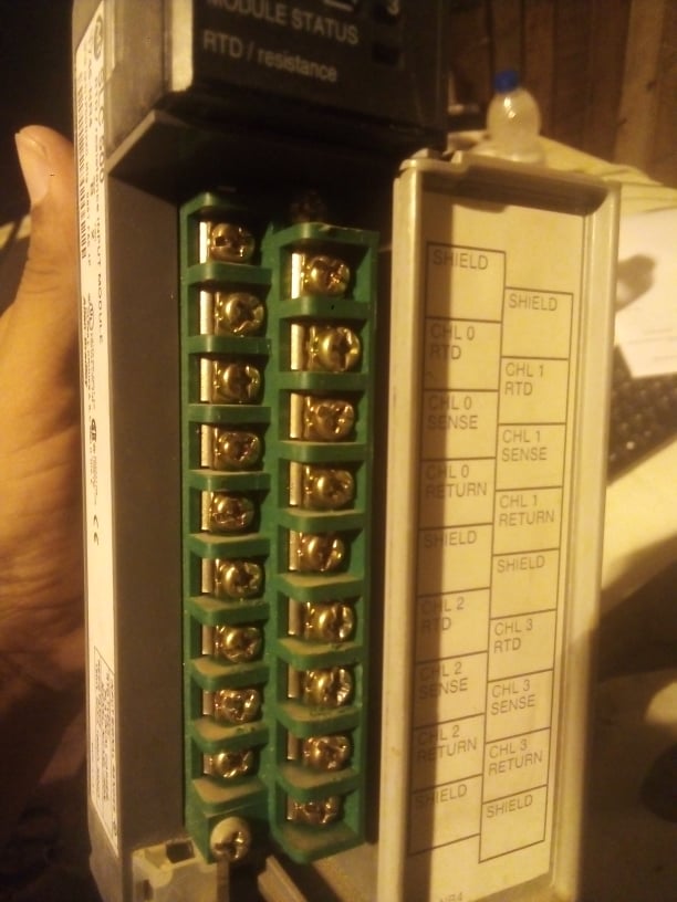
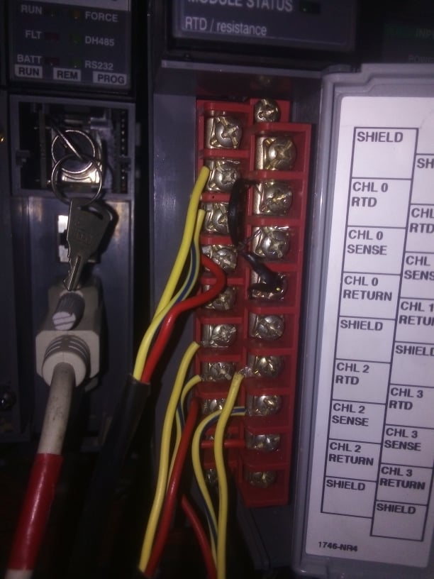
On 8/23/2021 at 3:52 PM, Joe E. said:I looked it up real quick because your question made me curious. According to Rockwell's Knowledgebase article QA11393 (Access Level: TechConnect for some unknown reason...), the green one was used for 1746-HSCE, -HSCE2, -IO12, -NR4, -NI8, -NO8I, -NO8V, -NI16I, -NI16V modules while the red one was for 1746-IA16, -OA16, -IM16, -OAP12. The article doesn't go into any other detail about any differences between the terminal blocks.
Page 171 of the user manual actually goes into a little more detail about which RTB to use for which module but, again, doesn't offer any details about the difference between them other than color.
These installation instructions seem to say that the color coding is there to help you avoid accidentally connecting the wrong voltage to the module. It only asserts that you shouldn't mix-and-match when it comes to thermocouple modules.
When replacing the module with a new one, I would loosen the screws that hold the terminal block to the module, leaving the wiring intact. The installation instructions (linked above) explain how to do that.
On 8/22/2021 at 0:47 AM, Mickey said:As Data would say "I could be chasing an untamed ornithoid without cause."
Thank you for your explanation. I find it useful
-
The printed info as follows:
GREEN RED SLC 500 SLC 500 RTD / resistance INPUT MODULE RTD / resistance INPUT MODULE 1746-NR4 1746-NR4 SER B SER B FRN 2 FRN 2 RTD TYPE: PLATINUM, COPPER.NICKEL,NICKEL-IRON RTD TYPE: PLATINUM, COPPER.NICKEL,NICKEL-IRON RESISTANCE: 150OHM, 500 OHM, 1000 OHM, 3000 OHM RESISTANCE: 150OHM, 500 OHM, 1000 OHM, 3000 OHM WIN (21) 1P0GN2X0 Mfg: 0897 FAC. 1P WIN (21) 1P0YJ9AJ mfg: 1002 FAC. 1P OPERATING TEMPERATURE CODE T3C OPERATING TEMPERATURE CODE T3C CLASS I, GROUPS A, B, C, AND D, DIV.2 CLASS I, GROUPS A, B, C, AND D, DIV.2 -
5 hours ago, DanW said:You're not color blind.
I am not color blind . The new module I bought from the internet and never expected the color
-
Hi,
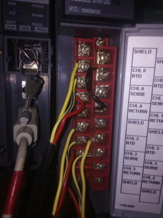
I have new RTD module the same specification as the old one however looking to the front face of the RTD a difference can be seen:
The old module is GREEN
The new module is RED
Anyone can tell me what this means?

-
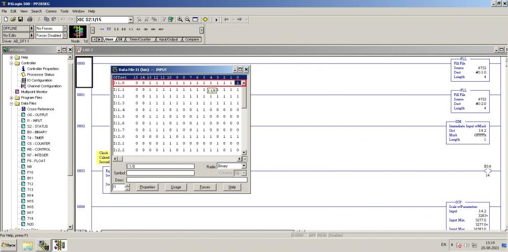
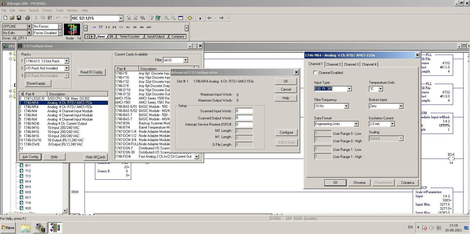
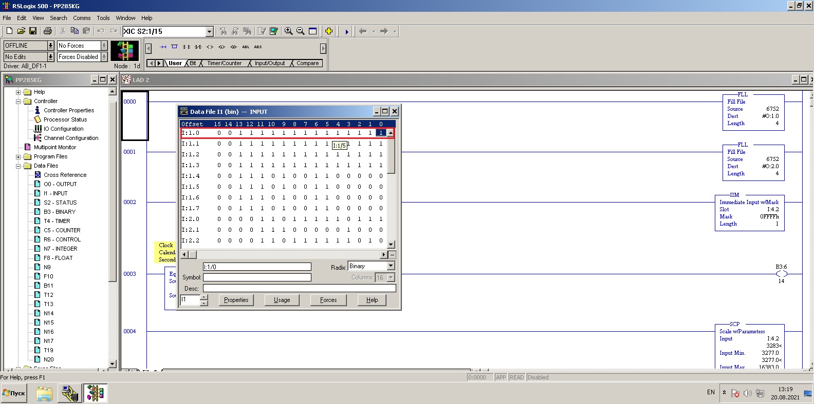
9 hours ago, Joe E. said:Your screenshots are from when you're offline with the PLC. You won't see the input table change unless you're online.
For your pattern of LEDs (module status is ON while channel statuses are blinking), the troubleshooting section of the user manual (1746-UM008B) has 3 suggestions:
1) Broken input condition (open or short circuit)
2) Out-of-range condition
3) Channel configuration error
If you get online, check the processor status file register S:6 to identify the I/O error code and use the instruction set reference manual (1747-RM01) to look them up. That may help you narrow it down.I am sure it is something that has to be done with channel configuration because when I swap this module with the next module everything becomes OK therefore nothing wrong with the field side
-
Hi,
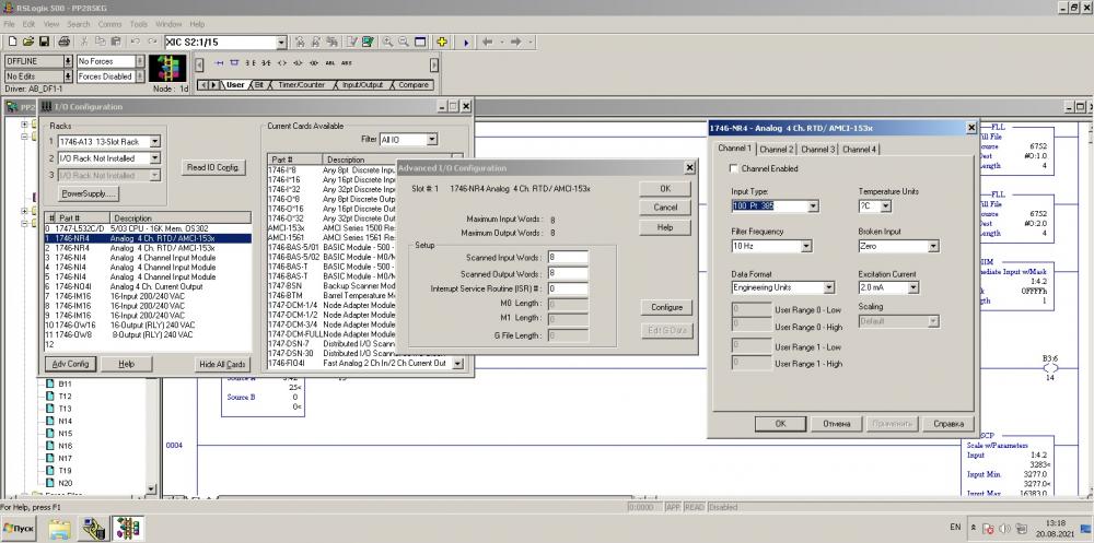
I have inserted new RTD module into in my SLC500 as replacement to defected RTD module however the module LED is enabled but the channel LED's are blinking.
I have checked the following:
In the advanced I/O configuration the module configuration is shown as expected
In the data file word format it is not corresponding to the channel preferences
What should I do and how to fix the word bits?
-
Hi,
I need help. How to get this software RSLogix500.
My Processor is SLC5/03 L532
-
Hi,
Anyone know places for selling AB products at reasonable prices in these countries: Turkey, Tunisia,
-
Hi,
Anyone using the subject legacy PLC in monitoring and control application and what type of networking and software being implemented?
-
Hi,
What would you recommend Ethernet/ip to DH-485 router?
Anyone with such experience in here?
-
On 8/7/2021 at 5:46 AM, alan_505 said:We have plenty of PvP's talking to SLC 503's and 504's in the plant I work in.
Alan
Whta is Pvp's?
-
20 hours ago, pturmel said:No.
RSLogix 500 for the SLC family + 176x MicroLogix.
RSLogix Micro for 176x MicroLogix only.
RSLogix 5000 for ControlLogix and CompactLogix.
RSLogix 5 for PLC-5 family only.
CCW (Connected Components Workbench) for Micro8xx family only.
You must use the correct programming software.
Thanx for the info. appreciated
-
22 hours ago, pturmel said:No.
RSLogix5 Pro may be?
1 person likes this -
On 8/5/2021 at 1:40 PM, alan_505 said:To get online or look at SLC files you will need RSLogix500, RSLogix5000 is for ControlLogix and CompactLogix not SLC processors.
Alan
Could RSLogix Micro starter do the work?
-
Hi,
I wonder if it was possible to use FactoryTalk View ME to design project for SLC5/03?
The hardware connection uses serial DF1
Could be any limitations due to CIP network protocol?
Any suggestions?
-
10 hours ago, pturmel said:Is "RSLogix 5000" typo? You need RSLogix 500, not 5000.
I do not have the RSLogix500 but I installed the RSLogix5000. Is there any way through?
-
9 hours ago, BobLfoot said:What model of pv-1000 can you post the part number.
It is 2711-T10G3
-
Hi,
What is the best option to replace the PV-1000?
-
Hi
I have established serial DF1 full duplex connection from my laptop to the SLC5/03. I am using Serial Null modem cable and it works because I can make the auto configuration in RSLinx Classic and I can see the SLC5/03
However when I launch the RSLogix5000 there is no chance to select the path to the SLC even though it is there in the list
Any help?

csv file - tags
in Allen Bradley / Rockwell Automation
Posted
In my project I have converted the original *.pba HMI files into *.med project and I can run some parts of the plant however looking into the tags I notice some tags are missing, others are replaced or modified
What is the best way to keep the tags as they are
I have the project *.csv file from supplier but can not load it with import tool
any idea?