Search the Community
Showing results for tags 'torque sensor'.
Found 22 results
-
Hi Everyone, I have a small project where I need to detect temperature and smoke using Allen Bradley Micro820 PLC and send email when the temp is above or below a set limit. And since I'm new to PLC world I'm not quite sure which sensors would work with my plc model. It would be really helpful if anyone could guide me through and suggest any sensors appropriate for temperature (surrounding temp not liquid temp) and smoke.
-
Hey y'all- I have an application that uses an Allen Bradley servo with a brake and a linear actuator to lift a plate vertically. While maintaining a position, the servo drive (Kinetix 5500) will occasionally fault due to over-torque. I'm thinking it could possibly be due to mechanical issues i.e. bearings in the actuator but my initial thought would be that it would fault while moving up/down as well, so far I've only ever seen it fault while holding a position. This leads me to suspect that there may be something off in the control loop. I'm not involved in the setup but I know we use load observer and I reckon we use auto-tune. Other than that, I wonder if it's something to do with the brake. I also read about mechanical resonance in the manual which seems like a stretch but it could be contributing, the frame that the actuator/motor is attached to does vibrate a fair bit. I'm familiar enough with basic motion control using Allen-Bradley and understand the basic concepts behind the servo/control loop. However I'm at a loss for why the servo/drive would spontaneously over-torque while maintaining a position. How would you guys approach troubleshooting this further/solving this issue? Many thanks!
-

Problem: Analog Input 4-20mA from Electromagnetic Flowmeter Sensor
Khoukou posted a topic in Other PLCs
I am using DVP-ES2 PLC with DVP04AD-E2. I connected the flowmeter to the analog input module (4-20mA). And I noticed something weird, when the flowmeter shows 4mA value (no water flow at all) the data in the PLC keeps coming like 20-30 (0-32000). And when I change to the other port of the analog input , it even reaches value like 100 although there is no water flow at all. Note: I have done proper scaling to Liter/second and do proper grounding. Do you know what is the cause of this? -
Has anyone used 2 Keyence PZ series or similar retroreflective sensors in parallel to detect on the closest distance of irregular shaped objects? It should work if my sensor-fu is correct, but in actual use, has anyone had experience with it, and are there any 'gotchas' to watch out for?
-
So I'm having trouble writing a FBD within my current program for a slitting line. I need to keep a constant tension on my web as it is being recoiled onto our recoiler. I wrote a simple program using a sensor to read the growing rate of the coil to get a radius and I have feedback on my torque on the recoiler motor. The simplest math for this application without getting into anything too fancy should be Tension(lbs)= Torque(ftlbs)/coil radius. only problem is when its less than a foot then my calculation is thrown off and it actually shows tension goes up until it reaches the one foot mark then it seems to scale correctly. Do I need to scale something else? Any help on this would be appreciated.
-
Help connecting BiSS C or IO-Link or SSI to EtherCAT (a Magnetic Sensor: SIKO MSA 213C)
Gemson posted a topic in Robots
Hello. I'm trying to help someone with a sawmill find a way to input from a sensor to connect it to the PC. Not sure where even to look to ask for help. but here's what I understand: The sensor is a SIKO MSA-213C Magnetic Sensor, using EtherCAT. This interfaces with SSI, BiSS C, IO Link They just need to connect it to the PC to work with it. It could just connect to a USB port somehow, or the etherCAT option. I found this: MB3U BiSS (SSI)-to-PC Adapter (USB) link to .de site any suggestions or pointers would be very helpful! These folks don't use the internet, so I help them. Jeff -
Getting this error while adding MC_TorqueControl. I want to control torque from HMI value. Using R88D-1SN08H-ECT drive and R88M-1M75030T-S2 Ac servo motor with NX1P2 PLC. Newbie Here. Please support. Error 1 The Axis parameter of the MC_TorqueControl instruction does not support single-axis position control axes. Program1 Section0 Row 6
-
Hi new to the forum, and first post, however, I have found an abundance of great information here, so I was hoping someone might able to help me with an issue. PLC is BRX BX-DME1-10ED13-D I am trying to read an analog output from a sensor that is capable of essentially outputting a mA signal proportional to where a printed line, or contrasting edge is at in its field of view. It is used for web guiding applications to make sure the web is tracking straight, so you can identify if the line or edge is moving to one direction or the other, and correct the web with an articulating web guide. I have attached the diagram for the sensor, but I cannot for the life of me figure out 2 things 1) The power supply to the sensor is listed as follows Supply current - From fife control +/- 12vdc 50ma (+)12vdc AND - 40ma (- )12vdc how do you provide both (+) and( -) 12VDC for the supply power to a sensor- 2 power supplies with the the opposite polarities grounded on each? 2) The outputs are listed as "Sum" and "Differential" so apparently there are two outputs, i dont know if anyone has come across these terms relative to sensors before, but I am trying to sort these out. According to the OEM Sensor Output Range -20 mA to +20 mA for line guiding -20 mA to +10 mA for edge Guiding I have attached the pin out diagram as well as the sensor spec sheet, but I am curious to see if anyone might have insight as to how I would get an analog input reading from this configuration? Thank you in advance for any help! 224615.pdf SE-26B Product Sheet.pdf
-
Hello i installed an powerflex 70 into a CNC Mill machine, and its works fine over 1000 rpms, but below that RPMs its like the motor loose torque. i think could be a sliping problem. its some parameter need it to be changed?. or any special parameter that i need to look out?. thanks for your help. Regards
-
Modbus addressing in Weintek HMI to poll data from Temperature sensor through RS485. In my system i have connected Temperature sensor to I/O Scanner has output in terms of RS-485 which directly connected to COM3 Port pin. No. 6 (as Negative) & 9 (as Positive) of HMI (Model No: MT8071iE) and HMI connected to PC via ETHERNET. I want to read temp on HMI screen via MODBUS protocol. So, can you please provide me instruction about addressing of MODBUS register in Easy-Builder Software so can read data of corresponding register. Because when i do compile i got an error like " Device no Response". I hope i will get reply from your side as Fast as possible to overcome this problem. Thank you.
-
Hi All, I am doing an application that use servo motor to feed plastic film to a target length (set by operator), and it need to stop immediately if marker sensor is ON. This application is control by Omron CP1E PLC. It will feed plastic film in 500-1000mm/s depends on the target length set by operator. It is require to stop immediately if the servo feed length more than 90% of the target length and the marker sensor is ON. However, is there any possibility for the servo to stop immediately once the condition is meet? As I am using PLS2(887) to feed with target length, and INI(880) to stop immediately, however, it cannot get the desired result as servo not able to stop immediately after marker sensor is ON, I am not sure is because of the PLC scan time, or servo need time to deceleration (deceleration rate assigned to #FFFF). Appreciate anyone able to assist on this. Thank you.
-
Hi Everyone..I'm having hard time to read Analog Sensor. I've try to read the manuals about expansion module, but still having hard time to understand it. My PLC is CP1E-N30DR-A connect with Expansion CP1W-MAD44 and I'm trying to connect with pressure sensor Omron E8F2-B10C that in a certain pressure will trigger to open a Digital Valve. is there something wrong with my setting for range? I do the setting in 4-20mA (0-5V) I attached my Program and Picture while running, the program is only for reading the pressure sensor. the result is -600 to +600, is there a way to earn the actual result? I've tried Scaling and APR, But didn't understand, is there a guide/tutorial for it as well? Cheers.. Albert TEST.cxp TEST.cxp
-
Need Help - Change sensor to accurately detect box jams
MaintDude posted a topic in Allen Bradley / Rockwell Automation
Hi guys....first post here. It's been about 6 years since I worked heavily with PLC's and automation, but I'm getting back into it. I was hoping you might be able to help me with an issue I've noticed at work. Problem: The sensor we use just reads if there's something there, or not. A make or break if you will. When boxes are pushed together and there is no gap between them it thinks there's a jam (after 6 seconds) even when the boxes are moving past (as they should). A jam stops the conveyor belt requiring someone to physically move the boxes to clear the sensor and restart the equipment. I'm trying to find a sensor that will see the distance changes from box to box (mounted on the side of the conveyor). Only when there is a true jam and the distance isn't changing will it send a jam signal. I've tried researching sensors and have been overwhelmed by the endless possibilities and combinations (not all of which I understand). We are currently using an Allen-Bradley 42EF-P2RJB-A2H It would be ideal to have a similar style plug, but it isn't a deal breaker. Here's an idea of what I'm dealing with. (The actual conveyor the jams are occurring on is a decline belt, not a roller accumulator.) There are varying box sixes, but they are all packed together. Creating a gap between boxes or using metering belt is not an option here. Thank you for any help/guidance you can offer! -Steve -
Twincat 2 with Motion control (Maxon motor) and torque sensor
TwinCAT Newbie posted a topic in Other PLCs
Hi, I'm new to TwinCAT 2 and i'm upgrading a long time design (hence the TwinCAT 2 reference), to read a more sensitive torque signal. I'm using a Beckhoff CX1030 as my PLC Controller. I needed to add 'homing' to my motor sequence and confirmed with Maxon, im using the function blocks correctly and in the correct sequence to establish my 'absolute zero'/'home' position. The motor has an output to write to: ControlWord, which tells the motor that the position it is sitting in is '0.' My program compiles, it runs, it writes each function block, but it's not seeming to get back to the test run opMode, even though i tell it to and the function block performs the 'Write' function. it's stuck at zero and not reading an analog input signal from my torque sensor. so im getting an artificial torque reading through every test. i think this is related to my tare motion. I start the program, home the motor, get into profile velocity mode, tare my sensor, enter profile position mode, go back to position 0, then back to profile velocity mode, run a test, sample data, go back to 'home' or '0.' I wonder 1st, is my variable not linked properly through the system manager? 2nd, i set a boolean variable to set the 4th bit to 1 in my control word write (setting the 4th bit high will set my current position to absolute zero), but did i not connect the program to the main sequence properly? looking to read a valid signal again and see that my motor moves back to 'home' each time. Do i not need to home the motor after the tare, since the tare nulls out the torque value after the tare? after this i need to program my sample period, instead of it being fixed, as it is currently written and then use my home position as my trigger to start sampling.... Beckhoff applications department is overloaded, currently and can't help and this is all beyond the knowledge of the general support line. I've gotten fairly far, on my own, but of course, the project is under a time crunch. Does anyone know twincat well enough to help guide me? -
I first saw AS-i at a factory this week and am trying to figure out what Allen Bradley modules can interface it. I am not finding anything, does AS-I go under some different name?
-
Tooth gear pulse sensor connection to Allen-Bradley automation system
Jiggadoo posted a topic in General Topics - The Lounge
Hello! Does anyone have experience of using tooth gear pulse sensors. I am looking for this kind of sensor for the machine, we are building. My problem is that the sensor we are using is not suitable for North American markets (UL-standard is not aproved) and now I am searching sensor like this. I am not sure is inductive sensors good enough for measuring this, the one that we have been using is magnetic field pulse sensor. -
I'm looking for some general information about different types of vibration/temperature sensors. What type, brand, model number, etc. will best fit my application. Scenario: I want to monitor the vibration and temperature of multiple motors and gearboxes for a large overhead conveyor system. If an oil leak occurs and temperature increases, I want to see a temp. alert via a HMI. If a something mechanical fails, I want to see a vibration alert via a HMI. I've looked into sensors that stick to the outside housing of the motors or gearboxes via a magnet. My concern is justifying the temperature readings. How accurate would a sensor that reads an "ambient" temperature be (compared to a thermocouple on the motor coil itself or some sort of probe)? Also, would the location of the magnet on the motor or gearbox drastically affect the temp. or vib. readings? Has anyone had success with a similar setup? If so, what devices did you utilize? Are these systems truly beneficial? I'm currently considering Banner's wireless products...
-
Hi, Recently, we replaced our old digital temperature transmitter with a Baumer Flextop 2201 digital temp transmitter. The application of the digital temp transmitter is for a hydraulic press and the output is fed to the Siemens S95-U plc. The Flextop was able to react properly promptly when there is increase in temperature but whenever there are sudden drops in temperature it is slow to react. The analog transmitter (dial) was already at 25 C when the hydraulic press was shut down while the Flextop was still at 35 C. We used a three wire configuration for this. Does this have to do with our wire configuration? I know there are 2 wire ,3 wire, and 4 wire configurations for 4-20 ma sensors but I'm not sure what are their differences among them. Please see attached configurations below. Thanks,
-

Temperature measurement using Arduino Nano, RTD PT100 temperature sensor and 4-20 mA transmitter
Absolutelyautomation posted a file in Other PLC Demo Software
Version 1.0.0
130 downloads
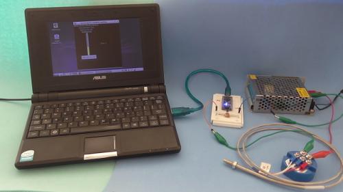
Temperature measurement usind Arduino Nano, RTD PT100 sensor, 4-20 mA current loop transmiter, and a python app for visualization -
[Other PLC Demo Software] - Temperature measurement using Arduino Nano, RTD PT100 temperature sensor and 4-20 mA transmitter
Absolutelyautomation posted a topic in Download Comments
View File Temperature measurement using Arduino Nano, RTD PT100 temperature sensor and 4-20 mA transmitter Temperature measurement usind Arduino Nano, RTD PT100 sensor, 4-20 mA current loop transmiter, and a python app for visualization Submitter Absolutelyautomation Submitted 04/01/16 Category Other PLC Demo Software -

Developing a block moving system with Flex i/o and control logix
ConfusedStudent2016 posted a topic in Allen Bradley / Rockwell Automation
Hello, I am new to this forum and I am looking for some help. I have to create a block mover system using the controllogix , I know that I must use a SQO as I have done this process without a Flex I/O on a SLC 500 before. Currently I am getting a error while dealing with the array can anyone show me an example of a SQO in 5000? Thanks -
Hi ! I have a question regarding the handling of the signal from the TS102 connected to my PLC. I downloaded a .pdf LINKED from "my omron", read it and put together a small program just to test the expansion unit and sensors. But I cant get any readings from the sensors and can't figure out why. I have never used a TS102 expansion unit before and would be glad if someone have an idea of what I'm doing wrong. Everything is brand new, so I'm quite sure I am the problem here..... If someone have an answer and maybe even an programming example to upload I would really appreciate it. Best Regards! PT100 sensor test 3.cxp