Search the Community
Showing results for tags 'timer counter'.
Found 86 results
-
Hi.. I found very hard to make Unlimited counter for application that i trying to make.. My application it's empty pack system.. On packaging machine.. This counter is supposed to count finger at machine... When it reach its value.. It will reject.. Coz theres sometimes many empty product thats entere the package.. I make more than 5 counter..i try to make loop...the problem is.. When 5 counter already workw.. Sometimes when its start.. It doesn't want to count again.. I have to wait for 1 cycle.. Than it work again.. Does anyone knows how to solve this... Thank you
-
Hye, I new in this plc understanding. For now I have this one ladder diagram that created in mitsubishi GX Developer that I use in winding machine as its plant. But, I have to make the FUNCTION BLOCK DIAGRAM for this part in CX Programmer. Can anyone help me how to construct the FBD in CX Programmer from this ladder diagram understanding . And did it is actually the counter function ? *the picture showed the ladder diagram*
-
Hi all, I try to realize a cycle timer. A counter is triggered by a movement ( clamp close ) Then the machine does it things, piston here, and there and when the clamp closes again it should show me the real cycle time. Is there a timer/counter that is independent from the PLC cycle? I am using a CJ1M CPU11 Ver. 3.0
-
hi every one! i'm new with PLC mitsubishi, i have a Fx3u board and using Gx developer i can config input interrupt pointer in GX developer but i don't know how to config timer interrupt with GX developer. i have read a lot of manual but i don't understand... someone can help me?????
-
Hello everyone! Could someone help me and tell me what the "D212" means? I know that to define the time of a TIMER you must put a k and number (miliseg). Help.... :(
-
Hi I put value #80 in word 60 I run timer 2 with word 60 I replace word 60 withe the value #10 I run timer 2 again with word 60 but you see the timer counting down from 80 instead of 10 So the timer runs first the previous value of word 60 before he runs with the new value although you see the new value of word 60 appearing in the timer. How can I let the timer run immedeatly with the new value. Thank you
-
I tried setting parameter in gx works 2 for plc q series of q03ude cpu. I set retentive timer to 1k and reducing special link relay to 1k from 2k. then I set 0 in latch 1 start and 5 in latch 1 end. Getting error c4129 and c4139. I changed it to just 16 points of device, then put 0 in latch 1 start and 15 in latch 1 end, still getting same error code. In mitsi pdf of basic course, it just said all I have to do is to go to parameter>device>set retentive timer value to 32 from 0 to use 32 timers total, but I just simply getting error code of f1028 How to make it right? Got it now, have to uncheck retentive timer in tools menu.
-

How should I go about doing an 8 hour timer?
KevanB posted a topic in Allen Bradley / Rockwell Automation
Didnt know this before but should have anticipated it, I cant put 8 hours into say a TON or a TOF, etc. Only goes up to 2880 seconds, .8 of an hour. What would be the best way to go about this? -
Hi everyone, I need some help with my PLC programming. I am currently using a twincat 2 software and a Beckhoff CX 8090. Basically, the gist of my program is to send and receive data and datalog the input data received from the sensors and timestamp the received data for every 1 second. I want to create a boot up counter where it will count the number of times my data logging program has restarted(if it did). This boot up counter serves as a health monitoring check to ensure that my program is running perfectly and thus, not restarting randomly when it shouldn't. I am more familiar with structured text so if you have a solution, kindly post it in structured text form. Your help would be greatly appreciated. Best regards, DeadPool
-
Hi, everyone, I started learning very recently, and I have been writing this little program in which I communicate through RS-232 with a machine. Every time I send a command from the PLC I wait a couple milliseconds for the machine to send a response (a response must always exist, even if it's a mere acknowledgement response), then I save the response that the machine has sent. I organized my ladder logic by the commands that the PLC has to send to the machine (4 commands total, for example: execute this, give me status on that, etc). I started every ladder with an OSR and an AWA instruction, and when AWA is done I have a timer in the next rung to wait for the machine response, and after timer I have a ABL activated when TON is done. The Ladders are related in the sense that the end of each LAD contains a JSR instruction to the next command/ladder. So the commands/ladder always execute in a predefined sequence (LAD2 -> LAD3 -> LAD4 -> LAD5). The logic inside each ladder is like this (the last rung is a little different for the others, this is LAD2): ] start [ ----------------------------------------- [ OSR ] ] OSR OUTPUT BIT [ -------------------- [ AWA ] ] AWA/DN [ ---------------------------------- [ TON ] ] TON/DN [ ----------------------------------- [ ABL ] ] ABL/FD [ ------------------------------------ [ ARL ] ] test if ARL string is 0 [ ----------------[ JSR ] 1) Since I have to use timers so often in my program (they all last for the same period of time) I wonder if I could use the same timer every time (same Control File R6). But I'm quite lost on WHEN I would have to reset the timer, or if this would not be recommended at all, since the timer is still counting for more than one scan. Although I want to believe that the timer for that Ladder would never be counting after the JSR instruction, I think this is true only for the first time since the next time I turn "start" ON the ARL is not zero, so JSR would occur while the timer is still counting. I tried resetting my timer parallel to JSR and using the same timer in the next ladder, but then the timer only counted up for the first time "start" goes ON (I believe because the timer was constantly being reset at every scan). 2) Also using OSR with AWA was the only way I found of making AWA and TON to "behave" (that is, to make AWA only go ON once per start and the timer to go ON every time AWA is DONE). Would there be a better way to do this or is this acceptable? When I tried connecting "start" to AWA directly the program just didn't behave the way I expected at all, I believe because AWA would always be enabled for more than one scan, although I cannot explain why this would be a problem since AWA should only execute from the transition false to true, no? 3) I never clear my buffers or reset my ASCII instructions... when I try to clear in parallel with JSR some of the ASCII instructions' bit ER goes ON, and when resetting my ASCII instructions sometimes I don't see any before/after difference, but oftentimes I just see an undesirable behavior, and to be honest I'm not even sure where in the code I should do it, so I wonder if I should bother. More specifically, in which situations should I care about doing it when writing a program, and where in the program is it recommended to do it? So far I don't seem to have a problem, so I'm being willingly ignorant about it Any suggestion regarding my code/logic is much appreciated! Thank you!
-
Hi guy ! I have a problem with plc omron cp1e.Please every body help me. I was used high speed counter to count clock of encoder. And I want to count up/down pulse input case.But it not excuted.also if i use pulse + direction them it ok I used CX programmer. Thanks all
-
Hi! I just started with PLC programming. I am trying to get the time between a output signal and a input signal. The problem is that the time is ~200 ms but when i measure it with this code: TONR(Timer1); IF PosFeedback <= PosFeedback_Min & not Timer1.Reset THEN Timer1.TimerEnable := 0; FullCloseDeltaTime[1] := Timer1.ACC; Timer1.Reset := 1; END_IF; IF (move & not Move_LastScan) THEN //Start timer Timer1.TimerEnable := 1; Timer1.Reset := 0; END_IF; Move_LastScan := move; i only get even values in intervalls of 50 ms like 150, 200 and 250 ms. I have changed the real time sample rate to 11 ms so i don't understand why i don't get a more exact result. And i can see in my trend that the time isn't exactly 150, 200 or 250 each time. I i tried and time my own click on a button and i see the problem is the timer, i only get values in an interval of 50 ms. Is there a way to make the timer more exact?
-
LD I0.0 EU ATCH INT_0, 21 ENI LDN M0.0 A I0.0 TON T32, +1000 LD T32 = M0.0 LD I0.0 ED DTCH 21 DISI INT0 LDN Q0.0 = Q0.0
-
Hi, I keep getting an error that project is in binary mode and plc is in BCD mode. Wont let me change either. I must be trying in the wrong place...please point me to where i can change this in the PLC. I am getting an error in my RXDU with a Honeywell barcode reader, on one machine, I am thinking it is related. thanks for any help.
-
Hi: I urgently need a simple sample Counter Interrupt Program to study and implement with my machine. I am using GX Work 2 My Problem is inconsistent start stop of roller conveyor after pulse count (OUT_C_32, with cc235, using CC235 to stop a conveyor.) I have to try interrupt, but the manual sample is suck! Please help Tks
-
How to use analog values in SoMachine Basic?
mgn posted a topic in Modicon / Telemecanique / Schneider Electric
I'm using TM221CE40T PLC with TM3DI16 DI extension. I'm programming it using SoMachine Basic. In the program I implemented a counter (%C0). I've read in the documentation that %Ci.V stores the current count value. I want that to display this value on a Magelis HMIS5T. How could I store the current count value (%Ci.V)? Thanks in advance! -
hi: in Omron that is a command to count how many bit that are in ON state, any similar instruction in GX Work 2? Thanks
-
Version 1.0.0
208 downloads
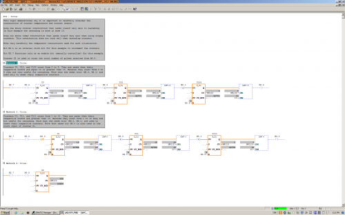
This logic demonstrates the construction and cascading of counters that count from 0 to 9. This logic also illustrates the construction of counters that count from 1 to 10 (not useful for cascading). The difference is mainly in the comparators used to reset the counters. There is one small additional detail. Can you find it? -
View File FC3 Counter Demo This logic demonstrates the construction and cascading of counters that count from 0 to 9. This logic also illustrates the construction of counters that count from 1 to 10 (not useful for cascading). The difference is mainly in the comparators used to reset the counters. There is one small additional detail. Can you find it? Submitter pop29684 Submitted 03/24/16 Category PLC Sample Code
-
STEP7 Professional V13; FB Declaration Static: Data type TON is not allowed here
Traloch posted a topic in Siemens
Product: STEP7 Professional V13 Reference: FB Declaration Static: Data type TON is not allowed here Description: ++++++++++++++++++++++++++++++++++++++++++++++++++++++++++++++++++++++ Hi, I'm using Step7 Prof V13 SP1 upd7 & WinCC Adv V13 SP1 upd7. In my project I'm using a 312CPU, Article No.: 6ES7 312-1AE14-0AB0, Version: V3.3 & TP1500 Comfort, Article No.:6AV2 124-0QC02-0AX0, Version:13.0.1.0 My Issue: I've taken previously used FB from my Global library and inserted it into my new Project. In this FB I've declared an IEC Timer (TON) in the static section of the FB. When I go to upload to the PLC after TIA carries out the compilation I get error message 'Data type TON is not allowed here'. I've tried creating a new FB to test and had same issue for CTU,CTD,TOF. See attached pics This is really strange as it has always functioned before! Has anyone seen or heard of this issue before? I'd appreciate any help, Cheers. -
Hello, I hope you are all having a great Wednesday. So I was wondering if this is possible, and if so, how to do it. What I'm trying to do is get a real time speed of my hydraulic cylinder using a transducer, a 1769-HSC high speed counter module, and a 1769-L36ERM processor. Kind of like a speedometer in my car. I would like the number in inches/ second. We use a hydraulic proportional valve to control a cylinder that we use to pump molten lead into our die cast machines. Back in the day they used to use limit switched that rest on a tail rod attached to the cylinder shaft to get an approximate stroke length. It was very crude, but it worked for what it was. I'll explain a little more, in case I'm not explaining it very clearly. So on most of our machines the maximum stroke length of a normal shot is about 11". We have different "stages" to the shot. Stage one is typically from 0" (when the shot is all the way returned) until about 1.5", at 1.5" the valve stops and there is a shot delay for 1 second (vacuum draws some lead into the goose neck and into the beginning of the mold), after the delay second stage starts, second stage is from 1.5" to 4", third stage is from 4" to 8" and fourth stage is from 8" to 11.5" or until the shot timer finishes timing, and then another valve switches, and the shot starts it's return. We have the different stages because we typically shoot the cylinder slower at first, and then delay and then almost maximum velocity. We control the velocity with an analog output to a solenoid on a hydraulic valve. For example, for the first stage we may open it up 20%, then 0% during the delay and then 85% during second, third and fourth. Sometimes we play around with different shot delay times, different shot velocities, sometimes 3rd may be faster than 4th, ect, to get the best die casted parts. Anyways, so in the past they would use limit switches. One was a button head style that when the shot cylinder shaft was all the way returned, it made the switch, and we knew the shot was fully returned. One was set at 1.5", 4", 8" etc. They all, except for the shot return switch, were roller style limit switches. They were all made, and once the shot reached that stroke length, they would come off the rod and we would know we were in that next stage. So it was very crude. If you wanted to adjust the stages you would have to climb up on top of the very hot molten lead pot, mark where the limit switch currently was (in case you needed to put it back) loosen the bracket, try to make a measurement and guess how far you moved it. It was crude to say the least. Some of our older style machines that don't need much tweaking still use the limit switch style positioning system. Most of our new machines all use a VisiTrak transducer. The shot cylinder rod that is attached to the cylinder shaft is actually threaded and then has a very thing layer of chrome plating. The transducer sits against the shaft and counts the threads. It transfers those counts to a Very High Speed Counter module in our PLC I/O rack. We have a CompactLogix L36ERM processor and we use a 1769-HSC as the VHS Counter. Then we just do some math in the PLC program and we are able to get shot stroke in inches. We set different compare instructions, for example when: Shot_Stroke is greater than or equal to 0 AND Shot_Stroke is less than or equal to 1.5 then 1st_Stage_Bit is active. We set up different numbers for all the different stages and still use the button head limit switch as a second method to confirm that the stroke is fully returned. The counter is very fast. We are able to know what the shaft stroke is at any given point. We currently do some math using the distance of each stage and using timers to calculate inches per second of each stage. That way we can have a nice Speed number in inches/second that we can use to make different adjustments to the shot. Typically the first stage is about 7"/second second is: 24"/second third is: 42"/second and fourth is 2"/second. But I want a real-time, current speed, not just the speed that it traveled through each of the stages. Ok, after all of that explaining, I'm finally getting to my question. How would I logically write a set of instructions that could give me current speed in inches per second. Like i said, I am able to calculate the speed of each stage, after the shot has completed the stage, I just divide the distance of the stage (in inches) by the time it took to travel through that stage (in seconds). But I would like to have a real time speed, kind of like a speedometer on a car. Is this possible? I know that the scan time on this processor is very fast and the high speed counter module counts very fast as well. How do I do the math to get a real time speed in inches/ second? Sorry for the very long post. I just thought i would give you a background on what we are doing/ would like to do. Thank you very much.
-
GX Works2 Timer Example View File OUT_T on of delay timers in GX Works2 Submitter HwT Submitted 12/12/15 Category PLC Sample Code
-
-
Hi, I am new to the forum and relatively new to PLC's and I am working on a project that controls several pumps and I would like to install a off delay timer that can be adjusted on the HMI for individual pumps, is this possible ? I am using Siemens TIA Portal V13 and I have a KP1200 comfort panel along with a S7-1500 PLC Any help would be greatly appreciated
-
Could anyone tell me that how can we use/recall Q bit of timer in FP0R. As we can use DN/TT in Allen Bradley