Search the Community
Showing results for tags 'pt100 cx-one cx-programmer temperature measure'.
Found 149 results
-
Hi! I have this CQM1 CPU21 plc running but the problem is that I'm not able to communicate using CX Programmer V9.5. Under the "Backup PLC" section, the drop down list for the specified PLC is not included. Is there any update/software to be use in order to communicate the PLC? I have "USB to RS232 Cable" that I have been using for different PLC, I also have this OMRON CQM1-CIF02 Interface Unit that is not also working upon communicating the PLC. I'm thinking that the software itself has a problem or needs an update. I hope someone can help. Newbie here in OMRON PLC. Thanks!!! Marky
-
Hello to everybody! This time I need to make a program to control temperature ... Some help? I don't know how to use an analog module, I'm just starting to working with them. The PLC I have a FX3u-32MR/ES (Mitsubishi), and I have the modules; FX3u-4AD-ADP and FX3u-4AD-PT-ADP for temperature measurement. PLEASE HELP? Have a good day!
-

PLC program pulled from Taiwanese machine not Displaying Comments Correctly.
ggudino posted a topic in CX-Programmer
Hello, We have a machine from Taiwan that we are troubleshooting. I pulled the program with comments, from the PLC. It looks like they used a combination of English and i'm assuming Chinese. The problem is that the Chinese is not displaying correctly. It displays as symbols like @, ©, and other keyboard symbols. I was wondering if anybody knows what I have to do to display the comments correctly? Do I have to install a CX-ONE Chinese language pack or a Windows language pack? If I need a language pack, where can I get it and will I easily be able to go back to English when I'm done? I've emailed OMRON but it seems that they are very slow with their support. Thank you for any help in advance. -
Hi, im from brazil and need some help, some days ago i buy a programmer CQM1-PRO01-E beacause one plc CPM2B are deceased, we have another equipaments with this one, but CX programmer not response and de are trying day after day, but with this programmer i want copy and paste the logic from other PLC. Can you help with copy and paste on programmer CQM1?
-
Hello guys, I have gotten to a level where I can do a few things with an OMRON PLC. However, there's something that is supposed to be basic by now but I still don't understand it, and I will appreciate your help on this . What is the difference between the D, W and H memory areas of the PLC? And in what instances do I utilise each of them for storage of my data? Thank you.
-
Hello, I would like to make single ethernet connection with a cj2m cpu31 and an ns8 screen. What exact setting are need to set at the cpu and at the screen project? Is there some kind of quick guide which shows where to click etc? I dont want to read 700 pages and didnt found a proper manual, maybe you know a good one? Thanks in advance!
-
Hello! Is it possible to run a program only 1 time when i turn on the plc? In siemens it was ob 100 or soemthing like that, that program only runs one cycle at startup of plc. I want to make sure some bits are off at startup to be in safe position Thank you for your help!.
-
Hello, I have a cj2 plc, and i would like to use two pt100 to measure, and just show the results on an hmi screen. I started to look at the Cat. No. W396-E1-03 SYSMAC CJ Series CJ1W-TC@@@ Temperature Control Units manual, but i don`t understand fully, that is these card are only for temperature controls? What is the easiest way to have the readings? it doesn't need to be the cheapest solution. And especially how is the programming works? Is there a special unit are i read about but how is the adressing works? Im completely new to omron (i know siemens) so any linked guides are welcome!
-
Good day I have a CJ2M cpu with ID211 module I have 2 E6B2-CWZ6C encoders connected to inputs 6,7,8,9 the plc data trace shows that pulses are being read, but I`m trying to configure PRV 881 instruction but it doesn`t work please find attached the images Best Regards Eduardo encoder error.pdf
-
Hello, My quest is to make a memory card, which I can just put into my PLC on the field and load all program and options etc to my plc. Now i found the official omron guide about it but its not good at all... For example is does not explain that how i need to transfer the H and D memory part to the plc, and that not all network settings are being copied if im not careful. But my question is: is it possible to make this backup memory card without having the actual plc? Because the process is done in memory card window, which is only available if you are online. So basicly i have to get all the plc rack parts to make this work? I tried with the simulator but ofc it is not working. Someone mentioned me that it is possible he heard from someone but no one actually knows how to. And there is nothing in the omron manual as i see.
-
hello guys, When i simulate the programme,using CJ1M CPU21, and i set contact 200.01 and 0.01 on, the KEEP doesn't change the bit of adress 200.01 to 1. The same thing happens to the KEEP below. Can you give us a reason for this problem and show us the way. Best reggards, yolo.cxp
-
hey! I'm pretty new to PLC's, and I'm supposed to ''teach'' the people at my internship how this PLC works, but I have encountered a problem. I've gotten pretty far with all the digital programming and understanding how everything works, but I just can't figure out how the analog inputs/outputs and programming works...... I've had a fair explaination on PID and how this works. I've searched the web as well to figure out what PLC instructions to use. I hope you can answer my following questions. 1, what are the most used PLC instruction blocks which I can use for temperature control, and how am I supposed to use them? 2, Could you please give me an example on how to use PID and what numbers will I need for the calculations? 3, what are the most used PLC Instruction blocks (apart form the analog ones) that I should include in my tutorial? this is my setup: Ethernet switch MOXA EDS-205 Plc voeding PA202 PLC CPU CJ1MCPU11-ETN Digital IN (16x) CJ1W-ID211 (SL) Digital IN (16x) CJ1W-ID211 (SL) Analog IN (8x) CJ1W-AD081 (SL) Analog IN (8x) CJ1W-AD081 (SL) TRANS OUT (16x) CJ1W-OD212 (SL) TRANS OUT (16x) CJ1W-OD212 (SL) Analog OUT (4x) CJ1W-DA041 (SL) thank you soo much for looking at my question and considering helping me! the OMRON helpdesk hasn't been very helpfull. kind regards, Deuslupos,
-
Hello! My name is Gabriela. First, I do not speak very good English. I have to do a project! I have a HMI (NQ3- TQ000B) to OMRON for a teaching platform. I installed NQ Designer for it. I did the program in CX-Programmer . But I have a misunderstanding. How can I connect the CX with NQ . How can I assign internal bits set from CX-Programmer in buttons from NQ-Designer? In the end, I would like that after I connected bits with buttons and I transferred the program to HMI, when I push the button on the HMI interface, the platform to do what I programmed in cx.
-
Hello, The company that I work for wanted me to design and build a FIFO loader. For those who do not know what a FIFO loader is, it's basically a lift that runs up and down and filling up the magazine slots with pcb's. After I finish the mechanical part i'll try to program it by using a CPM2C - 20. I have already played with CX-programmer and learned my self a bit, for example how to program simple things such as AND and OR gates for controlling motors and lights. Really hard part for me was figuring out how to create a program that reads data from the encoder and use it to create positions which the motor will stop at, and i have not yet figured it out. I've been trying to google it without any luck, the only thing of real info i've got is a 650 page long pdf file or CX-Programmer manual which is hard for me to read since i'm new to all of this. Would be great if any of you people got any source or maybe a manual which are easy to understand for new beginner like myself. A bit about the program i would like to make: The FIFO loader will have some buttons for selecting different programs, lets say you press first button to select "program 1". Then the machine should move up and stop at posision "50" (there are 50 slots on PCB magazine) after it gets signal from pneumatic actuator (which will be used to shove pcb inside the slot) its should move to position "49" and so on.. If FIFO loader is located at "home" position and you press second button to choose "program 2", then it will move to slot "49", wait until it gets loaded, and continue to slot "47" and so on.. The meaning of this is to make a loader which can select a program to fit pcb's with different size of components.
-

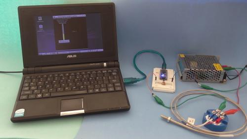
Temperature measurement using Arduino Nano, RTD PT100 temperature sensor and 4-20 mA transmitter
Absolutelyautomation posted a file in Other PLC Demo Software
Version 1.0.0
130 downloads
Temperature measurement usind Arduino Nano, RTD PT100 sensor, 4-20 mA current loop transmiter, and a python app for visualization -
[Other PLC Demo Software] - Temperature measurement using Arduino Nano, RTD PT100 temperature sensor and 4-20 mA transmitter
Absolutelyautomation posted a topic in Download Comments
View File Temperature measurement using Arduino Nano, RTD PT100 temperature sensor and 4-20 mA transmitter Temperature measurement usind Arduino Nano, RTD PT100 sensor, 4-20 mA current loop transmiter, and a python app for visualization Submitter Absolutelyautomation Submitted 04/01/16 Category Other PLC Demo Software -
PLC Programmer - fulltime position in Los Angeles
kmagel posted a topic in For Sale, Employment, Services or Wanted
Well established manufacturing company is looking for a PLC Programmer to join its team. The company builds, maintains, and repairs all of its production machinery at their plant in Culver City...very hands-on opportunity. Ideal candidate will have PLC programming experience associated with custom-built automated equipment. Must be authorized to work in the US (US Citizen or Permanent Resident). Responsibilities Troubleshoot and maintain PLC programs and control systems of custom-built automated production machinery. Replace and upgrade old PLC's and control systems. Design and program PLC based control systems of new machines. Requirements AA, BS, or Trade School degree in Electrical Engineering or equivalent preferred. Minimum 3 years experience in electrical engineering and industrial automation systems design and PLC programming associated with equipment/machinery. PLC programming experience with any of the following PLCs: Automation Direct, Festo, Allen-Bradley strongly desired. Experience troubleshooting machine control circuitry, motor controls, servo drives and associated systems, pneumatics and hydraulics. Location: Los Angeles (local candidates preferred) Salary: up to $80,000 + employee benefits including medical, dental, vision, and 401k. -
Dear colleagues and siemens experts, I''m new in siemens. As all I make my program for PLC, but I need help with PID autotunig (pretuning) I use : 1.CPU 1214C DC/DC/DC (6ES7214-1AG40-0XB0) 2. 6ES7214-1AG40-0XB02. 16IN/16 OUT DC/DC/DC (6ES7-223-1BL32-0XB0) 3. 2x 6ES7231-5PD32-0XB0 ( 4 channel RTD analog module - PT100) We use 7(seven) Pt100 points with 7(seven) heaters ... so I need 7 additional outputs..... [you can see example of wiring in attached pic 6es7231-5pd32-0xb0-modules.jpg] Maximum heating point is around 220 degrees. I make my configuration for PID_Compact : 1. Basic settings 1.1 Controller type : Temperature : °C Set mode to : Pretuning ( sometimes I make it Automatic mode) 1.2 Input_Per(analog) -----> Output_PWM 2.Process value setting: 2.1 Process value limits: Process value high limit : 220.0 °C 2.2 Process value limits: Default 3. Advance setting 3.1Process value monitor : Default 3.2 PWM limits Minimum ON time : 0.5 sec Minimum OFF time : 0.5 sec 3.3 Output value : Default 3.4 PID parameters : Default I start Commissioning with these steps : 1. Measurement : Sampling time 0.5 Start 2. Start PID_Compact 3.Tuning mode : Start When I try first time my setpoint was 90 degrees , second time I try with 120 degrees. After 4-5 hours it stop more in Progress bar it stop when I reach a little more then 50%, and I stop PID. For heaters it is not normal to process to be 4-5 hours, there have some wrong. Example with 120 degrees : During process I make : When Input_PER reach 120[1200] degrees I stop physical access to heaters. When Input_PER reach 100[1000] degrees I start physical access to heaters So 4-5 hours is soo long time for this type process. Time to reach 120 degrees from 100 degrees is around 2-3 min. Time to fall from 120 degrees to 100 degrees is around 4-5 min. Total time for one whole cycle around : 8min. Sometimes when I set setpoint to 140, 150 degrees it writes me that output set value is to high after I give Start Pretuning ? Even sometimes when try for 120 degrees .... As all I want to start PID pretuning (autotuning) with setpoint 140 - 150 degrees. Which are minimum requirement to start PID autotuning with PID_Compact ? Could you send me some very simple example and steps that I must make or only steps ? I attached files in dropbox with images and program example, because I can't attached nothing here. This form don't give me access to attached something. So link is here : Even program is there. Thanks in advance Best regards : Altan
-
Hi! I can not understend how to work with array from functional blocks. For example, I want to create some functional block (on ST lang.), send to it some array and recive from it some new array (FB make some monipulations with input array). FB code: FOR i:=0 TO 4 DOinputLoadArray:= outputLoadArray*2;END_FOR; How does look my main program (only on ST language) for send input and recive output arrays?
-
What is Omron naming convention for PID settings? I need to adjust the upper MV limits for PID running on CJ1W-TC001 installed on CJ1M-CPU13. Looking at the CJ1W-TC001 Operation Manual I am not really sure which values would these be. I guess Omron naming nomenclature is a bit different than what I am used to. It seems that the Manipulated Value Monitor is just feedback, which value would I need to set or modify to adjust the upper MV limit?
-
Hi everyone, Im quite new into OPCs, I'm using adam 4015 6channel RTD module to measure temperatures and then connected to adam 4520, I would like to know how to connect the adam modules to cx designer (or if have to make any program in cx programmer) as i want to have a GUI of the temperature measurement. Thanks in advance
-
I'm new to Omron, and after several days of diving into manuals trying to figure this out on my own and giving myself a headache I've come to accept that i need help. my task is the following: Control of the discrete and analog inputs/outputs in a DeviceNet system using an Omron CJ1M PLC’s and PT’s. Use at least one thermocouple, one analog input, and one analog output for the DeviceNet network. Use a pushbutton and a light for the start of the process and an indicator for the started process. I have a Drt1-Ad04 input, a Drt1-ad02 output, and a Drt1-ts04t temperature control. My devicenet is Cj1w-drm21, The Omron system itself is a cj1m-cpu13 etn21. I have node addresses for my input, outputs and temperature control, those being 35 for input, 25 or 30 for output and for temperature control 5, 15, or 20. The ip address im using for this project is 142.214.143.9I'm using Cx programmer, Designer and Integrator. On Cx programmer I've managed to create an IO table but i have no idea on how to begin the program or even get a current reading from my generator.On Designer I've made what i believe to be the layout of the pushbuttons, I just have no idea of what addresses to enter.And on integrator i'm having troubles on figuring out how to make a routing table. I've went through many manuals and either i'm missing something really basic here or I just have no idea on what I'm doing. The only advice I was given was to dive into more manuals and find my addresses for my inputs, outputs, and temperature or to find the information from an outside source be that a forum or customer service. I am able to provide more information, and screenshots of what I have done if needed. Any kind of help would be greatly appreciated!
-
Hi everyone! I have this simple problem, but cant get over it. I have structured ladder/FBD Project and i use GX works2. As topic tells I use analog signal from field. Now, i need to compare this value X (from field) to Values X1 and X2, meaning if value X is between values X1 and X2 then M1 is true. Ok, but what function i need to use for this? Best regards, Juha.
-
Hello all I have a task to connect a auxitrol l20d to my omroan plc i have these moduls: CJ2M - ID211 - OC211 and MAD42. The l20d should go from 18-5mA and when it hits 5mA a alarm should go off, my problem is how can I adress the inputs/outputs in the MAD42. My wiring to the L20D is this : The l20d is connect to A1 5-6 with + at 5 and - at 6 How can I adress the anonlog inputs in MAD42. Could anyone help me, or maybe give me an example program? Thanks in advance ;)