Search the Community
Showing results for tags 'protocol macro'.
Found 43 results
-
Hi everyone, Can any one share me the sample source code for melsec(MC) protocol, as I am working on this protocol. Thank you in advance
-
Hi everyone Is SLMP protocol and MC protocol are same?? what is the difference between these two protocols?? Thank you in advance
-
Hi. When i activate adress H417.14 in the PLC i want the system adress LB9012 to be activated. Do I need to make a macro to do this? I have never used macro before, and I do not know how it works. Please let me know if you have some solutions. For the record I am an apprentice, and neither me or my co-workers have an sollution.
-
Hello all, I'm using MC Protocol Format 4 to communicate with a VB6 application on a PC. I want to make some slight modifications, and I am getting a sum check error being returned by the module to my application. I believe (haha) I am calculating the sum check code correctly for Format 4 as most commands do work (reading for example). I was wondering if anyone knew of the buffer memory location on the QJ71C24N card that stores what the card is calculating for the sum check? This way I can have a troubleshooting tool to see what I am calculating wrong. I have looked through the manuals (application/basic) for the C24 already as well as the Melsec Reference Protocol manual. I have attached the error code for reference, again, I am only looking for what the C24 calculates as the sum check code. Thanks
-
Hello! Anyone here know about Fuji Electric power monitoring unit F-MPC04? Does anyone have the Communication Manual for this unit? I need to find the F-MPC Protocol which it used with RS-485. I know it is accessible via MODBUS RTU, but there is already a system exist using this F-MPC protocol. It seems Fuji doesn't publish this protocol for public, but there should be a document somewhere :D If anyone knows please kindly reply here. Thank you
-

[Manuals, Tutorials] - Q_L MELSEC Comms (MC) sh080008l.pdf
kaare_t posted a topic in Download Comments
Q_L MELSEC Comms (MC) sh080008l.pdf View File MC Communication Protocol Submitter kaare_t Submitted 06/14/16 Category Manuals, Tutorials -
-

Disable BOOTP on built in ethernet port
GeraldTech posted a topic in Allen Bradley / Rockwell Automation
It's another BOOTP post! I know you're all as excited as I am, so lets get started. But seriously, I'm trying to disable BOOTP on the built in Ethernet ports, not on an Ethernet module. I specifically say disable because BOOTP successfully assigns the IP address to my Compact Logix, however I still need to disable BOOTP to make it a static IP address rather than a dynamic IP address. I'm going to list everything that I have tried, so that anyone with the same issue can have an all-in-one-place reference. (Because there's a number of forum posts and other information for this topic on the internet, with many different suggestions) If I see different ideas/suggestions in other places, I can edit them into this post. Things I have tried: (and you should try if you have this issue) Disabling all firewalls, (For me: Windows/Avast) Disabling all other network adaptors. (Wifi especially, but any and all adaptors you are not using for the setup) Using a different laptop/operating system: (My current laptop runs windows 8.1 and uses a Linksys usb to Ethernet device to talk to the PLC, I tried a laptop running windows 7 which communicated using a built in Ethernet port) Lastly: Try to use all available methods to disable it. For me, that would be: BOOTP standalone server, RSLinx, (Trying to use both USB and Ethernet connections) and finally RSLogix. (Actually, only Ethernet modules have a "disable BOOTP" checkbox built into RSLogix, so that is not an option for me.) [If you have an Ethernet module, go to port configuration in RSLogix and uncheck the "enable BOOTP" checkbox] Anyway, RSLinx Classic (version 3.71) and BOOTP Standalone server (version 2.32) are each coming back with an error when I try to disable BOOTP. I'll attach a .jpg of some screenshots, and some Wireshark save files to show what I mean. In the RSLinx Wireshark file, it shows a "privilege violation" packet being sent from the PLC to the laptop towards the end of the exchange, but I'm not sure what privileges the laptop needs/doesn't have. For the wireshark files: I cleared everything happening before I try to send the command, so that there isn't a ton to search through. As far as timing of the wireshark files go: I start recording traffic, send the disable command (by clicking the disable BOOTP/DHCP button on BOOTP server or "apply" on RSLinx) then I stop recording traffic once I get the error message. So, the captured packets should be just the attempt to disable BOOTP and that's about it. I am sorry that I the pictures are strung together using paint, but I don't have photoshop on my work computer so it's the best I have. Any suggestions/help would be appreciated! (Regardless of whether they are suggestions for me, or suggestions that I may have missed intended for anyone with this problem.) Thank you for your time. Edit: I had the attached pictures open in paint/photo viewer, sorry that they look bad in the forum picture viewer. BOOTP_wireshark.pcapng rs_linx_USB_wireshark.pcapng rs_linx_wireshark.pcapng -

Video Game running in an Opto22 PAC using RFB protocol and VNC
Absolutelyautomation posted a file in Other PLC Demo Software
Version 1.0.0
1 download
Video game application running in an Opto22 PAC using RFB protocol and VNC client as interface, can be played with the Free simulator PAC Sim -
[Other PLC Demo Software] - Video Game running in an Opto22 PAC using RFB protocol and VNC
Absolutelyautomation posted a topic in Download Comments
View File Video Game running in an Opto22 PAC using RFB protocol and VNC Video game application running in an Opto22 PAC using RFB protocol and VNC client as interface, can be played with the Free simulator PAC Sim Submitter Absolutelyautomation Submitted 04/01/16 Category Other PLC Demo Software -
EATON Cutler-hammer Incom protocol forImpacc systems for HMI/SCADA
Scadadoctor posted a file in Other PLC Demo Software
Version 1.0.0
2 downloads
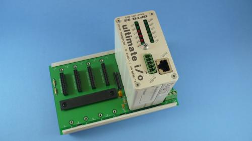
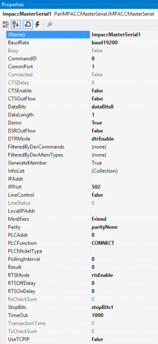
The Eaton cutler Hammer Incomprotocol for Impass systems driver from Parijat (ParImpacc), supports communication through serial or Ethernet ports to Eaton Cutler-Hammer devices using Incom or Impacc protocols, as a Master format. The driver enables users to capitalize on the low cost of communications equipment for use as the backbone for a power monitoring system and power quality analysis. ParImpacc can communicate with any serial via MINT or Ethernet viaEMINT device (Master Industrial Communications Network Translator), equipment as breakers, digital meters or motor overload relays. It supports communication with MPCV, IQ 200 & other Eaton devices. The IMPACC protocol module is designed to communicate with devices that use the ASCII version of the INCOM protocol to communicate with a host. Features : Host-to-RTU commands supported: 2024 -300 Get Fast Status 2025 - 305 Get Current Buffer 2026 - 308 Get Power Buffer 1 2027 - 309 Get Power Buffer 2 2028 - 30F (00003B) Get phasingVoltage 2029 3A4 Get INCOM Statistics 2030 3C8 Get Flags Buffer 2031 3C9 Get Setpoints This driver can be conviniently used with Visual Studio in development of complete large scale complex HMI/SCADA Systems. It can be used to perform advanced reporting MES, analytics, IoT, Big data type apps. One example is available to download here For More Info Overview of Parijat Drivers: Click here Additional supporting Info about Parijat Drivers:Click here Complete Related Driver options: Click here -
[Other PLC Demo Software] - EATON Cutler-hammer Incom protocol forImpacc systems for HMI/SCADA
Scadadoctor posted a topic in Download Comments
View File EATON Cutler-hammer Incom protocol forImpacc systems for HMI/SCADA The Eaton cutler Hammer Incomprotocol for Impass systems driver from Parijat (ParImpacc), supports communication through serial or Ethernet ports to Eaton Cutler-Hammer devices using Incom or Impacc protocols, as a Master format. The driver enables users to capitalize on the low cost of communications equipment for use as the backbone for a power monitoring system and power quality analysis. ParImpacc can communicate with any serial via MINT or Ethernet viaEMINT device (Master Industrial Communications Network Translator), equipment as breakers, digital meters or motor overload relays. It supports communication with MPCV, IQ 200 & other Eaton devices. The IMPACC protocol module is designed to communicate with devices that use the ASCII version of the INCOM protocol to communicate with a host. Features : Host-to-RTU commands supported: 2024 -300 Get Fast Status 2025 - 305 Get Current Buffer 2026 - 308 Get Power Buffer 1 2027 - 309 Get Power Buffer 2 2028 - 30F (00003B) Get phasingVoltage 2029 3A4 Get INCOM Statistics 2030 3C8 Get Flags Buffer 2031 3C9 Get Setpoints This driver can be conviniently used with Visual Studio in development of complete large scale complex HMI/SCADA Systems. It can be used to perform advanced reporting MES, analytics, IoT, Big data type apps. One example is available to download here For More Info Overview of Parijat Drivers: Click here Additional supporting Info about Parijat Drivers:Click here Complete Related Driver options: Click here Submitter Scadadoctor Submitted 03/10/16 Category Other PLC Demo Software -
Rockwell/Allen Bradley ethernet communication Protocol/driver
Scadadoctor posted a file in Demo Software
Version 1.0.0
223 downloads
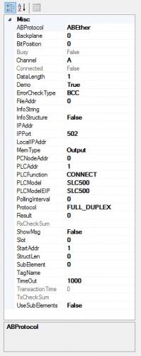
The Allen-Bradley Ethernet Driver provides an easy and reliable way to connect Allen-Bradley Ethernet devices to Client applications, including HMI, SCADA, Historian, MES, ERP and countless custom applications. This driver supports the Allen Bradley SLC 5/05 series, PLC-5 series, ControlLogix, CompactLogix, and MicroLogix PLCs. Features Interface: TCP/IP Ethernet Port, DHRIO, Net-ENI PLC Supported: AB Controllogix, Compactlogix, Micrologix, SLC50x, PLC5, via TCP/IP Ethernet built-in or Module port. Any device with Ethernet/IP protocol. Methods: Open, Close, RefreshInfo, ClearDataBuffer Events: OutCome (fires when a communication transaction completes) , RXComplete, TXComplete General: Also Supports unsolicited messages from SLC, Clogix family. Via DHRIO, access SLC & PLC5 data tables for read/write. Read or write most of the AB data types. support for DataQueue reads in SLC and Micrologix Throughput: Reads 100 consecutive registers @ 10Mhz in 40 msec. This driver can be conviniently used with Visual Studio in development of complete large scale complex HMI/SCADA Systems. It can be used to perform advanced reporting MES, analytics, IoT, Big data type apps. One example is available to download here -
[Demo Software] - Rockwell/Allen Bradley ethernet communication Protocol/driver
Scadadoctor posted a topic in Download Comments
View File Rockwell/Allen Bradley ethernet communication Protocol/driver The Allen-Bradley Ethernet Driver provides an easy and reliable way to connect Allen-Bradley Ethernet devices to Client applications, including HMI, SCADA, Historian, MES, ERP and countless custom applications. This driver supports the Allen Bradley SLC 5/05 series, PLC-5 series, ControlLogix, CompactLogix, and MicroLogix PLCs. Features Interface: TCP/IP Ethernet Port, DHRIO, Net-ENI PLC Supported: AB Controllogix, Compactlogix, Micrologix, SLC50x, PLC5, via TCP/IP Ethernet built-in or Module port. Any device with Ethernet/IP protocol. Methods: Open, Close, RefreshInfo, ClearDataBuffer Events: OutCome (fires when a communication transaction completes) , RXComplete, TXComplete General: Also Supports unsolicited messages from SLC, Clogix family. Via DHRIO, access SLC & PLC5 data tables for read/write. Read or write most of the AB data types. support for DataQueue reads in SLC and Micrologix Throughput: Reads 100 consecutive registers @ 10Mhz in 40 msec. This driver can be conviniently used with Visual Studio in development of complete large scale complex HMI/SCADA Systems. It can be used to perform advanced reporting MES, analytics, IoT, Big data type apps. One example is available to download here Submitter Scadadoctor Submitted 02/28/16 Category Demo Software -
Hi, I am working on the following setup: External server connecting to PLC system via QJ71E71-100 Ethernet module and using MC protocolConnection via LAN cable (straight-though) between external server and QJ71E71-100 Ethernet moduleGoal is to pull data from PLC system via the use of MC protocol + 4E frame + ASCII data code + batch read Word units (via 0401 command, which is part of MC protocol)External server will act as TCP client, while QJ71E71-100 Ethernet module should act as TCP serverThe external server is using custom software (programmed in Python) to query/process response. At this moment I can 1) "ping" the QJ71E71-100 Ethernet module successfully, 2) connect to it via TCP socket and 3) send data via TCP socket. All is working well so far BUT I am not getting any data back from QJ71E71-100 Ethernet module. My setting are as follows: IP address of external server = 192.168.1.203 (it binds the socket to port 1500 of this external server when initiating communication). The external server will always initiate communication to query data whenever needed, FYI. IP address of QJ71E71-100 Ethernet module = 192.168.1.254, and it connects to port = 1500The Ethernet diagnostic tool indicates that my TCP packets are being received ("Total Number of Receives" increase every time data is sent), and that TCP response packets are being sent (increases in tandem with "Total Number of Receives" (apologies for poor picture quality): Would someone in the forum have experienced a similar issue (meaning that you could connect + send data from external server, but no data was getting sent back from QJ71E71-100 Ethernet module to external server? Are there some obvious mistakes in the configurations to the experienced eyes in this forum? For your information I am not using any gateway for the connection: it's a straight-through LAN cable from the external server directly into the QJ71E71-100 Ethernet module. Would such a setup work out of the box, or do I need to configure "Router Relay" or "Station No <-> IP information" within GX developer? Lastly I have not configured FTP, email or Interrupt settings, FYI. Thank you for your help, feel lost with this TCP connection issue. Regards to all forum readers! PS: find attached the pictures detailing configuration settings for both QJ71E71-100 Ethernet module and external server.
-
Hello, I am not familiar with the Omron PLC's. A PC is connected to the peripheral port of an CJ1M CPU12 PLC. The write command the PC is transmitting to the PLC looks like this (ASCII): "@00WD0070010055*." Can you tell me what kind of communication protocol it is using? It is a public or proprietary protocol? Thank you!
-
FT View ME v7 Startup Macro - Tags in Expression
DiGGy posted a topic in Allen Bradley / Rockwell Automation
I hope no-one minds that I'm cross posting this from the RA forums, I just wanted to get as much visibility as possible since there doesn't seem to be anything on the net about this. Any issue, let me know, or feel free to delete it. I'm trying to use a startup macro in my manual mode HMI application to copy the current state of my outputs to the inputs so the machine does not move or change state when switching between auto and manual modes. However, when I run the application on my PanelView Plus400 HMI, I'm immediately greeted with errors like "<macro expression>: Unable to read the expression""Read from <tag> failed"Some info: This only occurs for lines that set a tag's value to another's; if I set the tag to just a numeric value (like in the first line of the sample below), its executes just fine.There are two separate HMI applications. One is for normal / automatic operation. This one is to allow the operator to manually activate individual solenoids on the machine to aid with building, setup, and troubleshooting; it is not seen nor used in production.This occurs long after the plc has booted (manual mode is not the startup application) - so running anything on first-scan is not an option - and the HMI has no trouble communicating to these tags during operation.They are RSLinx Enterprise tags, I think - not HMI tags; they only exist in the controller / ladder. I'm able to successfully browse to them online in FTView.The expression editor reports the "tag = tag" syntax is valid.Lastly, I'm using FT View v7, but I'm creating v5.10 runtime applications.Here is an excerpt of the macro: {[Gage]MANUAL.MODE_ON} = 1;{[Gage]MANUAL.STATION_1_ESC_CLAMP_EXT} = {::[Gage]Program:Station_1.STATION_1_ESC_CLAMP_EXT_SOL};{[Gage]MANUAL.STATION_1_MOV_CLAMP_EXT} = {::[Gage]Program:Station_1.STATION_1_MOV_CLAMP_EXT_SOL};{[Gage]MANUAL.STATION_1_PROBE_EXT} = {::[Gage]Program:Station_1.STATION_1_PART_PROBE_EXT_SOL};{[Gage]MANUAL.STATION_1_ROTATE} = {::[Gage]Program:Station_1.STATION_1_ROT_180_SOL};{[Gage]MANUAL.STATION_1_SLIDE_EXT} = {::[Gage]Program:Station_1.STATION_1_SLIDE_EXT_SOL};... and so on...FTView IS able to successfully execute the macro when I test it on the development computer while it is connected to the PV+ over ethernet. If the PV+ is not connected, or the application is running solo on the PV+, no dice / same errors. I have also tried using HMI tags in all combinations in the tag and expression by tying the RSLinx tag to an HMI tag. So far, they've had the same results as above. Absolute worst case, I could edit the ladder to latches or unlatches the inputs off of a one shot from the manual mode on bit, but it would require 7 manual program changes across many in-production machines and would be very time consuming. I've searched everywhere, and the manual's not been any help - maybe I don't know what to look for. Thanks for your time everyone, ~Anthony -
Version
4354 downloads
W344-E1-14 describes the use of CX Protocol to create custom Protocol Macro sequences for CS/CJ ,Alpha and CQM1H PLCs.