Search the Community
Showing results for tags 'nj301 ip address'.
Found 35 results
-
Hi all, I am working on a safety PLC conversion project, for which I need to identify the input word address configured on a PSS AI IP card. The manual from the official website shows the address configuration via a DOS tool. I do have PSS SW PG WIN 4.9, but the project file has been created with PSS WinPro 2.3. Within this software there is only the option to configure how the input channel behaves, not which input word is used (see attached screen grab). Anyone with a distant memory if the addresses can be set with PSS WinPro?
-

NJ301-1100 primary task timeouts after add EDS of Cognex scaner
aleksander posted a topic in NJ Series / Sysmac Studio
Hi I am new in Omron, most of time I spend with Siemens products so that's why I shyly want to ask about communication over EthernetIP in the case of PLC Omron. I am working with not my machine with PLC NJ301-1100 where are 3 axes on EtherCat, no nodes on Ethernet/IP, only HMI NA5. Primary task with cycle 500us (and additional periodic task 10ms but it is not important). I want to add Cognex scaner on EthernetIP. I use SysmacStudio. In first step I add EDS file and two structures IN (80bytes)/OUT(80bytes) to PLC, no algorythms. After downloading changes to machine in a while it stops with PRIMARY TASK TIMEOUT. With original program the task execution is ave 394us, max 467us. For NJ301 adding 160bytes is additional around 100us to communication cycle. Is that cycle part of each task (primary and others) or it is parallel proces? I am little confused. Additional communication time is 160*0,0015 + 160*0,56 + 2,15 + 7,5 = 99,49us. Am I correct? And this is the problem, I am out of the range of WatchDog? For now I didnt add any algorythms. In the future I will add new periodic task to PLC and this new InOuts will not be used in primary task. Thank You for any advice. ps I have found option for my inputs/outputs REGISTER TO SETTINGS FOR EXCLUSIVE CONTROL OF VARIABLES IN TASK. I created and chose new periodic task for them. Will it helps? I won't be able to check it until Monday so if You have any advices I will be gratefull ;) Best regars! -
Following my post from yesterday and the fix proposed by @chelton, I went ahead and expanded the solution to multiple PLCs in the shop. Now I'm stumbling on another layer of difficulty : I have to RECV in a CP1L-E (10.1.14.214) from a NJ-301 (10.1.46.118). Both PLC's are physically connected to the same Ethernet Switch in the shop, but the IT guys decided to add a new subnet for PLCs and equipment some time ago. I read Michael Walsh's answer on this post but I couldn't figure out how to set things up properly with 2 subnets that are not consecutive. What do I need to setup in the CP1L-E to be able to RECV properly? There is certainly a routing table setup that I need to add but I cannot figure it out by myself. Here is the current setup : In the NJ, I have a UINT variable mapped At %W0, Network Publish set to "Output" The RECV command in the CP1L-E is as follows: C0 = 0001 (1 word) C1 = 0001 (Port 0, network 1) C2 = 7600 (node 118, unit address 0) C3 = 0203 (port 2, 3 retries) C4 = 0032 (5 sec timeout) The Built-in Ethernet parameters in the CP1L-E are attached Thanks !
-
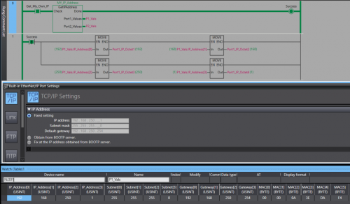
View File NJ/NX Get IP Address A Library containing a function Block that can be run on any Omron NJ or NX PLC. The Function Block will retrieve the host PLC's IP address, Subnet Mask, Gateway, and MAC Address. The Port Details are presented through 2 structures , 1 per-port. In the event the PLC only has one port the structure for Port 2 will be blank. Submitter photovoltaic Submitted 12/12/22 Category PLC Sample Code
-
Version 1.0.0
76 downloads
A Library containing a function Block that can be run on any Omron NJ or NX PLC. The Function Block will retrieve the host PLC's IP address, Subnet Mask, Gateway, and MAC Address. The Port Details are displayed through 2 structures , 1 per-port. In the event you only have 1 Ethernet port then the structure for the 2nd port will contain all 0s. Data Format: IP Address - USINT[4] Subnet - USINT[4] Gateway - USINT[4] MAC - BYTE[6] (hex value) Access the retrieved details by the typical parent-child tag structure. ex. Port_1_Detals.IP_Address[0] will get the first octet of Port 1's IP. Tested on: NX1P2, NX102, NX502, NX7, and NJ301 IMPORTANT: This Function Block should not be run immediately after startup. Allow the PLC a few seconds to establish a connection with the Ethernet network. -
Is there an efficient tool to manage and validate CX-Programmer addressing. Requirements: - Highlight Duplicate Address allocation - Compact/Defrag address range to avoid wasting memory space. Note: - Any FINS addressing will have to be reconfigured - This approach assumes symbol use rather than direct addressing in the logic.
-
Control Powerflex 525 with NJ301 with Ethernet/IP
ragzz1995 posted a topic in NJ Series / Sysmac Studio
Hello All, I would like to control Powerflex 525 drive with Omron NJ301-1200 PLC via Ethernet/IP (Set speed, start, stop). I've gotten until the part where I downloaded the necessary .eds files of the drive and imported into my Sysmac studio. However, I'm stuck after this point while assigning target variables and Originator variables and eventually setting speed and controlling the vfd. I've attached images for your reference. -
It will de nice to have an option for getting a cross-reference report for the AT address used on programs , as is now its easy to make mistakes double setting the same AT address on a program , specially this days that supplies of NA screens are not always availiable and using memory address is necessary for NB screens and SCADA communication and is difficult to keep track of the used address on a program , some times in global or in internals, right now its easy to make a mistake and use the same address twice , and this wont be detected on the compiling
-

Zebra Industrial Printer and Allen bradley L18ER printing via Ethernet IP
AniAutomationIndia posted a topic in Allen Bradley / Rockwell Automation
Mail me for Help if anyone is stuck during coding and settings. -
Dear, I am trying to setup an UDP connection between my Omron NJ301 PLC & my LED power supply CCS PD3-10024-8-EI (https://www.ccs-grp.com/products/model/3329). My setup: I Close all used sockets. I SktUDPCreate Socket 1 for sending messages. I Fill in DstAdr & DstPortNo to 192.168.000.002 & 40001 (I have pinged with cmd and the IP adress does respond). I Fill in the sendstring with "@00E01172.016.110.007A2CRLF" as per manual. I SktUDPSend this string. I clear the receive buffer to be sure it is empty. I Create socket 2 for receiving messages. I tried filling in only the Dst and filling in both Dst and Src but it has the same result. (DstAdr 192.168.000.016 & DstPortNo 30001) I SktUDPRcv without error then used a TON for 10ms before I check my buffer I Check my receive buffer and it is empty (Size 0) When trying to ping (by using laptop in same network) 192.168.000.016 it automaticly tries to ping 192.168.000.014 without succes. So my question: Is there another way then using 2 sockets? And does anybody have any clue what I'm doing wrong?
-
Hi I'm trying to set up Modbus RTU communication between FX3U PLC and a weigh module. I would use the ADPRW command using 0X03 to read the 16 bit Holding Register but in the weigh module the Data Address/Holding Register of the value I want to get is 400047 - 400048. How to translate the value in 16 bit? Thanks, Fabio
-
Communicating between plc's with different IP's
plcaholic posted a topic in Allen Bradley / Rockwell Automation
I am trying to get produced and consumed tags set up between 2 1756 racks with different ip's. The 1st rack has an ip address 172.28.6.3. The 2nd rack has an ip address of 10.81.105.8. Would this be as simple as adding an EN2T card to one of the racks and setting the ip of one onto the same network? Or is there a better way to do this? -
Hi guys, I've just completed pre-commissioning on a Mitsubishi project which uses CCLink. My remit was to get the CCLink network up and running which I eventually did but not without issues. Basically, my problem was to do with the number of bits and registers consumed by a station. I read in a manual that each station consumes 32 bits and 4 registers for read and 32 bits and 4 registers for write. On my network I had 3 ST1H-BT modules occupying 2 stations each and 3 non Mitsubishi devices occupying 4 stations apiece. My RWr address starts at W300 and RWw at W500. Like I said everything matched up and I/O checks completed successfully. My question is, and I've trawled through the manuals looking for an answer, how is the number of points calculate? For example my non-Mitsubishi devices they occupy 4 stations, Expanded Cyclic Setting is Octuple and the number of points is 896. How is the 896 calculated? Thanks in advance
-
Hello All I am new to sysmac studio, i am using a NJ301-1200 and R88M-KN10H servo drive , i connected the servo to the NJ using ethercat. I was able to write a program where i was able to activate the servo from the NJ using the mc_Power instruction . My question is , i am not able to run the servo using the mc_movevelocity and mc_moverelative . Do any one have any suggestion to how to go from here ..
-
Hi everyone My system consists of 2 main stations with 2 CPU Q06UDEH and connected together by QJ71GP21S-SX module but I don't know how to link the address between these 2 CPU together? so can anyone help me? Thanks so much
-
We have an iQ-r R08cpu that will not display some labels or addresses. The PLC and the machine it controls run as expected. However, when we read from the PLC, some of the labels and addresses are not shown. Although it runs as expected, we are hesitant to make any changes or write to the PLC. There is a screenshot attached. Any advice or solutions for this?
-
Hi folks, I'm trying to communicate with an old CompactLogix L35E via Ethernet. I have already establish communication via DF1 Serial port and was able to go online but I Do not know the IP address to communicate via Ethernet. Can someone please tell me how I could determine the IP Address or create a new one ? This Controller was remove from a working machine. Any help will be highly appreciated. Thanks, Anthony.
-
hallo all, I want to ask if I click "read PLC Data" the "points" will appear, I use the QY18A output module that uses 8 points but there is no choice, the smallest is only 16 points. so I can't put 148 in the "start XY" column ... will it affect the I / O address in the program?
-
IP/ Subnets and communication between subnets
Joseph 0028 posted a topic in Computer Help and Networking
Lets say i have a PLC, with a name PLC1 with IP/Subnet of 10.125.34.243/255.255.255.0 I have to communicate this PLC1 with 2 other PLC's, PLC2 and PLC3 PLC2 with IP/Subnet of 10.125.34.10/255.255.0.0 PLC3 with IP/Subnet of 10.125.46.10/255.255.0.0 I imagine that, all these three are in different subnets, and so there should be no communication at all, but when i tested it, PLC1 to talking to/from PLC2 and not PLC3. anyone know the answer to this ? How does it talk to PLC2 with different subnet, but not PLC3 which is in different subnet as well. -

Modbus address register exchange between Melsec-Q series PLC and ME96SSHA-MB Power meter
RV3.0 posted a topic in Mitsubishi
Please assist me with the following; regarding the ME96SSHA-MB Power meter data transition with Melsec-Q series PLC; We acquire to read various values on dedicated Modbus storage address registers at the simultaneous into a Melsec-Q series PLC via Modbus (TCP or RTU) for calculation purposes. Naturally, since the reading of these variables are to provide accurate instantaneous results, it is a requirement that these values are to be read at one scan. However, as can be seen below, there is a gap in address register range – of which, if all of these are scanned simultaneously, yields an exception error when read. This error is only avoided by scanning these data sets separately – which is not ideal for our application – since accuracy in calculations is imperative. -
Hi After updating CXS to ver. 3.4.1 I can't see point address I can see them when I editing but in the list form only the array len. is shown. When I enter a new point I can see the address. Anybody now hove to solve that ? Banker
-
Hello, I would like to see your logical opinion about this situation and in which part of system where I need to find solution - software or in the physical field. Subject: Twelve old system based on Mitsubishi PLC AnS series, Profibus Here is pneumatic transport, with 5 lines, each line have a shredder and discharge valve. A few months ago, when line 1 works , display shows line 2 and vice versa, it was first problem, but the system was still working. From the last week system doesn't work. On the display appear line 3 in works, but system can not started. Alarm shows Double address (perhaps two valves have some address), Alarm still appear after reset and even all lines are turned off. What is your opinion where to find proble (PLC, I/O moduls, cables,...)
-
Hello. I'm trying to communicate between two PLC's using FINS function block _CPU011:ReceiveData. PLC1: IP 192.168.1.50 (MASTER) PLC2:IP 192.168.1.51 (SLAVE) If I don't use »IP Address Table« everything works using NODE number &51. The problem is that on the real project these two PLC's will be on different subnet. For example: PLC1: IP 192.168.1.50 PLC2: IP 192.168.2.50 So I will have to use »IP Address Table« to achieve communication between these two PLC's. I tried to sett IP Address Table on MASTER: Node 1=192.168.2.50 But If I try to communicate I see that packet is sended to network but I've got error #1005. Do I have to sett the SLAVE IP Address Table? Hoe to do this? What are the right settings for MASTER and SLAVE IP Address Table? I'm attaching pictures of CARD settings. I don't want to use CX-Integrator because I would like to make project to UPLOAD and forget. Thanks.
-
Dear all, I'm first time using M580 (hotstandby). Now finish the configuration, but the problem is how to write the address for Digital Input, Digital Output, Analog Input, and RTD module in elementary variable ? I try to put name DDI_1 and the address is same with M340 topology like %I2.1.0.1.1 and for digital input but got message after build : {Elementary Variables} : The instance is located on an address that isn't configured. : DDI_1 Thank you for your advice regards