Search the Community
Showing results for tags 'motion axis move'.
Found 74 results
-
I want to run MR J3 A type 10 nos servo without using network, I'm to run servo using hardwired.please name motion controller to run 10 servo on hardwired..
-
Hi every body! Now I use a Q-motion controller Q172DSCPU with advanced synchronous control method. I try to synchronize 4 axes with Axis1 as command generation axis. The problem is that the command generation axis current value is not be cleared to zero after restarting the cycle. It should be cleared to zero to be kept within stroke limit during the process. Thanks in advanced
-
Version BA LBR iiwa V5
38 downloads
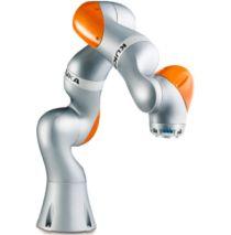
KUKA: IIWA is a collaborative robot with 7 axis, built in force sensors on all axes, built in mastering tool etc. -

[Robots and Servos] - KUKA: IIWA (collaborative robot, 7 axis)
panic mode posted a topic in Download Comments
View File KUKA: IIWA (collaborative robot, 7 axis) KUKA: IIWA is a collaborative robot with 7 axis, built in force sensors on all axes, built in mastering tool etc. Submitter panic mode Submitted 02/16/17 Category Robots and Servos -
Version BA KR QUANTEC PA V6
56 downloads
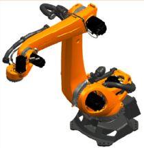
KUKA: Quantec palletizer -
[Robots and Servos] - KUKA: Palletizer (including Arctic)
panic mode posted a topic in Download Comments
KUKA: Palletizer (including Arctic) View File KUKA: Quantec palletizer Submitter panic mode Submitted 02/16/17 Category Robots and Servos -

A simple tutorial .smc2 project program for motion control (1) G5 servo
lamboom posted a topic in NJ Series / Sysmac Studio
hI.. I've asked for this in the past and, so far, haven't been very lucky. Most of the projects I run into have 4 or 5 axis, lots of analog and sensor input.. or don't have the HMI part of the "Machine" I have a nice NJ 101-1000 with the NA 7 inch HMI.. along with a R88BD-KNA5L-ECT servo and a 50W G5 motor.. type R88M-K05030H-S2. All On a nice rack with power supplies and some EtherCAT I/O (It all functions .. even "MC Test Run" gets the motor to jog .. But.. no way to "home" it.... The motor is in "rotary mode" but... it's NOT got an Absolute encoder.. it's a incremental... sniff! I just want it to stop on zero ..Or anywhere, and call it zero ... and make moves plus an' minus in degrees, that's all.... I assume I have to send it some signal (push button) while it's spinning that tells it it's in "Proximity" to home and it then it does something which makes it end up on zero. I've homed a lot of linear motors (LinMot) an' they are very easy to work with. But, Omron has 10 different homing modes .. and they aren't very well explained. Well, they aren't explained at all in that 502 page user manual... you have to already know how to do it, in order to understand the explanation... Example: Take the "Home Proximity Input Signal" .. I can imagine what it might do, to help control a move to home. I can even imagine what's making the signal .. and that somewhere there is a place where the homing parameters are set... like the "axis setting table" .. but, it's not a Global Variable, or a Data Type .. I could imagine it gets into the system from the CN1 I/O connector? or some I/O somewhere? But.. I grow weary of imagining how this system actually works.. Building a simple working project, from a tutorial, or even downloading a simple working project (.smc2 file) and making the minor adjustments to fit my equipment ... would make all the difference in the world. I've searched Omron's Libraries of .smc2 files. Haven't found any yet that aren't on the level of "Top Gun" (a seriously complicated project for a 1-week training class) ... Oh there are several.. related to IAG object files .. but those Library files are not "working projects" intended to serve as a Tutorial.. they are limited projects, ready to be configured with IAG Object files, and "your" programming ... So that you can write the programs you need "faster"... which is nice... but, no help here. Somewhere out there.. is a nice simple .smc2 project file where you get to control a simple motor from the HMI ..Preferably using an NJ CPU and a NA HMI .. home the motor.. jog the motor and input a few "go-to" positions... sigh!.. Like you would do in a One or Two Day class... This kind of thing should be already be available in the Sysmac Library ... Thanks much for listening.. sorry about the rant. -
I am trying to learn the logic of a process at my new job. There are tag names that I can't make sense of because they end with _xva, _xvb, _xvu, _xvd, _xvo, _xvc, _zsm, _zsu, _zsc, _zso, _zsd and so on and so forth. I know they are associated with motion, but I need to make better sense of them. There are no descriptors. What do they mean and is there a resource available that I can reference?
-

Getting UDT to work with physical IO
electric101 posted a topic in Allen Bradley / Rockwell Automation
Greetings, I'm here in my home lab trying to acquire a working knowledge of UDT's. I've had to work with them in the past in large existing programs and they were a pain to track down and find out what IO they were really controlling. I have a decent understanding of what they are and I've created several to play with here using my softlogix processor and a digital flex IO rack. My issue starts when i'm trying connect my UDT's to the physical IO. it looks like I cant use a simple move instruction (which would be way too easy and exactly what I need) I have a flex IO 8 point output. Local:1:O.Data[0] I have a UDT consisting of (see attachment) Valve001 Valve001.Out Valve001.Out.OPEN Valve001.Out.CLOSE Valve001.In Valve001.In.OPEN Valve001.In.CLOSED I have a copy instruction set to copy Valve001 to Local:1:O.Data[0] Length 2 that allows the Out.Open and Out.Close UDT's to control bits 0 and 1 of the 8 bit output . .... great. Now I have another UDT setup to control lighting... Door Door.Out.OPEN Door.Out.CLOSE I want to control bits 2 and 3 I make another copy instruction in a line before the original copy instruction that states Copy Door to Local:1:O.Data[0] Length 4 but i'm really just fighting for the same 2 bits that the valve controls.... how can I control bits 2 and 3 for the door/lighting logic using these UDT's? and that's not yet getting into having physical inputs moved/copied to the UDT input bits. thanks!! -
i need a example code for position control of MR-J3-20A with QD75D4 as intelligence module. and i want to see the parameter if possible
-
Just wondering if I need to set up two Motion Groups to specify the direction of travel along 1 AXIS? (Forward and Reverse) If not, how do I specify direction when using motion instructions (specifically MAM) with incremental motion.
-
Do I need an encoder (slave) axis for my project? I am using a Powerflex755 and Incremental Rotary Encoder (scaled into linear movement axis)... Any other suggestions would be GREATLY APPRECIATED!! project file https://sites.google.com/site/lyncedrgb/eva/untitledpost-2/StellaPLC.ACD
-
Hello, I'm new to this forum and PLC world in general (especially to Mistubishi PLCs). I have a task in which I need to synchronize servomotor with another motor that runs conveyer (servomotor needs to stamp a label on a foil on a conveyer), in GX Works3. Servo motor is run by Simple Motion module. I need general tips on how to make pulses from encoder into something useful that can be used to send data to Simple Motion module. I need high speed counter to count pulses (never actually did this, I got this from manuals), how would I, for example, get speed out of it? Number n pulses, divide it with time it took to get to n pulses? How would I make Simple Motion to make servomotor on his Axis #1 to rotate at same speed?
-
Hi guys, been using this site for a long time, it has come in handy alot. However I have recently taken on my first servo project, heres an overview of the project We have a filling machine that has a separate dosing system to the filler head. It used to keep the dosing in time by adjusting a 0-10v signal to an inverter to make sure that a flag makes a sensor in a set window. I have installed an encoder on the filling head and an mpl servo to the dosing. I have then used an MAPC instruction to follow the encoder, the cam is 0-360 and it follows a straight linear line. I have installed of this as a temporary set up on one of the filling machines (we have 2) and it is working perfectly. I have now installed this on the second machine as a permanent set up with a panelview plus 7, L71 cpu. However it is giving a very strange problem on first power up, the encoder is giving the exact same position as before it was powered down. however as soon as the MAPC executes the servo axis faults, giving an overspeed fault. the servo doesnt even look like its attempting to move (however it is through a 10-1 gearbox). if i then home the encoder it then runs absolutely perfectly until it is powered down again. I am beginning to think it may be to do with the master lock and cam lock position, as the cycle stop position of the two machines are different. however I just cant seem to get my head around i the difference between them. Hopefully that makes sense any help would be greatly appreciated Thanks Rhys c1_dosing.ACD
-
I need to learn about position control for 2 axis with a QD75MH2 module. I know how the basics about programming with the Q Series PLC but I've never done any positioning control. I'm having a really hard time understanding the program I have to modify and I don't know where to start. Is there any course you might recommend? Even if I have to pay for it. Thanks.
-
Hi: in Omron there is a command BSET which can be used to set value from DXXXX to DXXXXn. Example BSET #0 D2000 D30000 What is the similar command in Mitsubishi FX3U structure Ladder? thks
-
C200HW-MC402.pdf View File C200HW-MC402-E Motion Control Unit Operation Manual Produced June 2001 Submitter IO_Rack Submitted 03/09/16 Category Manuals
-
-
Hi guys! As the title explains, i wanna move a value to 210 -> 220... is there a function for that or do i have to make a MOV for every single dataregistry (look at picture)? Its an mitsubishi FX3GE PLC programmed in GxWorks2. Br, Jim
-
I am very new to PLC's, I work in a power plant and we have an ABB DCS. We have some vendors that use PLC's and they try to make them work with our system. Currently I am working on a project were I am trying to add 8 analog outputs to the PLC. I am working with two 1756-L71 controllers (redundant) and the rev for the program that was written 20.01. Basically I have 8 analog inputs that I want to bring to the spare analog outputs that I have. I want to see these inputs in our DCS. I wrote simple logic that at the end of the rung has a move block moving the source which is the input and taking it to the destination which I made an alias tag for the output channel that would correspond. Problem is I can see the source number moving, but the destination number stays at 0. I can type a number into the destination and it will work. I can see my 4-20 signal I am sending out in the DCS. Everything before the move function is true, I have and open contact, and a closed contact and they both are green. This is happening on all eight of my outputs that I am working on. Please help I have learned a lot from this experience but I cannot figure out what has me stuck this time.
-

1756-SYBCH not showing AXIS_CONSUMED tag in Axis 0
Coderblock posted a topic in Allen Bradley / Rockwell Automation
Hi All, I newbie in allen bradley usage. I am trying to configure 1756-SYNCH profile in RSLOGIX V21. According to help of "Associated Axes" tab, Axis 0 can support AXIS_SERVO, AXIS_SERVO_DRIVE, AXIS_CONSUMED, or AXIS_VIRTUAL. To cross verify, I have added AXIS_CONSUMED in my project but AXIS_CONSUMED tag is not showing in axis 0 choice selection. Can you guys please help me why AXIS_CONSUMED is not showing in choice selection of axis 0 and axis 1. -
Hi all. I have a B&R PP420 panel, some I/O on the X2X and 4 Acopos servodrives /servomotors. Successfully created and tested 4 axes, they work OK, control via NCtest or X2X IN, or PP420 display. But creating CNC system is the problem... On NCtest, I have errors, and no move. Error 7742: ACP10_MC FB error or aborted Info: Axis Index [0] Info: ACP10_MC FB error number [29226] Info: Command aborted [0] Info: ACP10_MC FB number [1] = MC_BR_MoveCyclicPosition (cyc. pos.) On SDM, axis error: 32274 Network coupling: The broadcast channel was not configured Can someone help? Thanks.svinaga@yahoo.com Foto errors.pdf
-
Dear Messrs., I need information to reverse engineer a GML diagram from the uploaded script. 1)Documentation for GML script language (iCODE ) Thanks,
-
I have a 2 axis control that runs a pair of identical servo drives. as of late I have been getting reports from the operators that the two motors, while jogging forward will suddenly run in the reverse direction at a high rate of speed. There is not a reversing function on these axes in an way. I am suspecting there may be a problem in the analog output of the module causing an inversion of the signal which in turn causes the motors to run in reverse. This setup has been in operation without any instance of this happening for around 5yrs before any issue with out of control runs. All cabling has been checked and is properly shielded and grounded.