Search the Community
Showing results for tags 'micrologix 1200 fault led blinking.'.
Found 143 results
-
Introduction to leguaje SCL senior siemens. When I use it for better optimization tasks, how to handle it and what its structure to be known as a language PLC Open. See more at http://www.tecnoplc.com/scl-lenguaje-estructurado/ PLC and HMI programming http://www.tecnoplc.com
-
S7-300 CPU is in STOP due to a Profibus failure. We have a facility with a Profibus master CPU and multiple modules with Profibus interface and when we insert the memory card with the CPU program does not change to RUN, it stays in STOP. Read more: http://www.tecnoplc.com/fallo-profibus-cpu-stop/ Greetings. _________________________________________ PLC programming and HMI http://www.tecnoplc.com
-

SLC5/05 fault when opening Cimplicity graphic
gromit posted a topic in Allen Bradley / Rockwell Automation
I hope to be able to provide more information, but for now this is what I have. I have a SLC5/05 that faults whenever a graphic display is pulled up from a Cimplicity HMI. So, the PLC is not faulted while all harnesses are connected to the I/O modules, and while the Ethernet cable is plugged in, but it appears to fault when a corresponding graphic is called up that includes tags from the particular processor. There are two PLCs on the network, and I am not certain if they share data between each other or not, or if the data is just being shared to a common Cimplicity HMI. Another strange thing is that one of the PLCs on the network is using a MSG instruction to pull data from what appears to be the PLC that continues to fault, but the IP address configured in the MSG instruction does not match. -
Hi, I have a ControlLogix L63 processor. We had a power outage the other day and the PLC went into Major Fault (Type 6, Code1). It is quite easy to find out what these mean (from vendor manual). However the major fault was reset before i looked at it, so i couldnt find any specific details on what routine faulted. There is GSV instruction in the fault handler to get the details of the Major Fault (MAJORFAULTRECORD). This recorded the TimeHigh, TimeLow, Code, Type and Info. I am now trying to determine what the date in the ".info" records mean (8 registers). I cant find this in any manual. Can someone help?
-
How to establish communication and TIA Portal PLC to detect the PLC within the network that we have defined in the project and thus be able to transfer the program to the CPU detected within this Profinet network. Read more... http://www.tecnoplc.com/comunicacion-plc-y-tia-portal-desde-el-proyecto/ Greetings. _________________________________________ PLC programming and HMI http://www.tecnoplc.com
-
CPU communication parameters set in the TIA Portal project to determine what range of IP be having. This address is the one that will be within the range of devices that can communicate within a network. Read morehttp://www.tecnoplc.com/parametros-comunicacion-tia-portal-ip/ Greetings. _________________________________________ PLC programming and HMI http://www.tecnoplc.com
-
hey can someone please help me with programming the plc to test on a code transmitted by a barcode reader thank you
-
Communication issues with PanelView C600 and MicroLogix 1400
python01 posted a topic in Allen Bradley / Rockwell Automation
I am working on a project with Micrologix 1400 and PanelView C600 I am not able to communicate over Ethernet with any device and my computer. I was not able to load the HMI screens so I don't know if they are communicating between themselves. The RSLinx does not see any device connected via Ethernet. I am using EtherNet/IP driver for this, not sure if that is right. I have tried connecting directly to each device from PC over ethernet and also connecting to them through switch. I can however ping each device and the packets are coming back. The IP assignments are as follows: 192.168.0.1 Router 192.168.0.2 PLC 192.168.0.3 HMI 192.168.0.25 PC Would anyone have any suggestions what I need to try to get this resolved? I was able to communicate with the MicroLogix via serial port but was not able to communicate with the PanelView through serial port at all. I have tried using the USB-2711-NC13 cable for the PanelView connection. Thank you. -
S7-1200 firmware load on the CPU once we have it inside the card. What is the process and sequence of LEDs indicating which CPU is running at all times. Have a look and red amore at... http://www.tecnoplc.com/cargar-firmware-s7-1200-en-una-cpu-6es7-214-1be30-0xb0/ You can find some more inforamtion about how to update firmware at... http://www.tecnoplc.com/actualizar-firmware-s7-1200-de-una-cpu-6es7-214-xxx-0xb0/ ------------------------------------------------------------------------------ www.tecnoplc.com
-
Using micrologix 1100 with panel view 800
Josh_Tech posted a topic in Allen Bradley / Rockwell Automation
I want use the panel view 800 with micrologix 1100 but i can't add the controller in connected component workbench. Exist another program to program the panel view??? -

Version 3.11.2.0
400 downloads
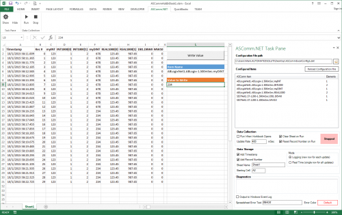
ASComm Excel Add-in is a simple to use, non-programmatic way to populate Excel 2007 - 2021 (version 16) spreadsheets with data from PLCs, instrumentation, and other process hardware. ASComm Excel Add-in uses built-in drivers for Siemens S7-200, S7-300, S7-400, S7-1200, and S7-1500 communications. No OPC, DDE, external drivers, or programming required. -

[Demo Software] - Excel Add-in for Siemens S7 Data Logging
Automated Solutions posted a topic in Download Comments
View File Excel Add-in for Siemens S7 Data Logging ASComm Excel Add-in is a simple to use, non-programmatic way to populate Excel 2007 - 2016 spreadsheets with data from PLCs, instrumentation, and other process hardware. ASComm Excel Add-in uses built-in drivers for Siemens S7-200, S7-300, S7-400, S7-1200, and S7-1500 communications. No OPC, DDE, external drivers, or programming required. Submitter Automated Solutions Submitted 03/01/16 Category Demo Software -
Version 3.11.2.0
518 downloads
ASComm Excel Add-in is a simple to use, non-programmatic way to populate Excel 2007 - 2021 (version 16) spreadsheets with data from PLCs, instrumentation, and other process hardware. ASComm Excel Add-in uses built-in drivers for Allen-Bradley ControlLogix, CompactLogix, MicroLogix, Micro800, PLC5, and SLC500 communications. No OPC, DDE, external drivers, or programming required. -
[Demo Software] - Excel Add-in for Allen-Bradley Data Logging
Automated Solutions posted a topic in Download Comments
View File Excel Add-in for Allen-Bradley Data Logging ASComm Excel Add-in is a simple to use, non-programmatic way to populate Excel 2007 - 2016 spreadsheets with data from PLCs, instrumentation, and other process hardware. ASComm Excel Add-in uses built-in drivers for Allen-Bradley ControlLogix, CompactLogix, MicroLogix, Micro800, PLC5, and SLC500 communications. No OPC, DDE, external drivers, or programming required. Submitter Automated Solutions Submitted 03/01/16 Category Demo Software -
hey can someone help me i dont understand how to communicate a DATAMAN60 with a PLC s7-1200 through an RS-232 communication the problem is with programming the module that contains the RS-232 port i dont know if the DATAMAN60 send data automatically or i have some programming to do thank you
-
Hi: I know how to update the S7-1200 by this link: http://www.tecnoplc.com/actualizar-firmware-s7-1200-de-una-cpu-6es7-214-xxx-0xb0/ , but anyone knows about update the Firmware with other type of Memory Cards??? Is it available with 12MB or 4MB card??? Thank you a lot.
-
Dear colleagues and siemens experts, I''m new in siemens. As all I make my program for PLC, but I need help with PID autotunig (pretuning) I use : 1.CPU 1214C DC/DC/DC (6ES7214-1AG40-0XB0) 2. 6ES7214-1AG40-0XB02. 16IN/16 OUT DC/DC/DC (6ES7-223-1BL32-0XB0) 3. 2x 6ES7231-5PD32-0XB0 ( 4 channel RTD analog module - PT100) We use 7(seven) Pt100 points with 7(seven) heaters ... so I need 7 additional outputs..... [you can see example of wiring in attached pic 6es7231-5pd32-0xb0-modules.jpg] Maximum heating point is around 220 degrees. I make my configuration for PID_Compact : 1. Basic settings 1.1 Controller type : Temperature : °C Set mode to : Pretuning ( sometimes I make it Automatic mode) 1.2 Input_Per(analog) -----> Output_PWM 2.Process value setting: 2.1 Process value limits: Process value high limit : 220.0 °C 2.2 Process value limits: Default 3. Advance setting 3.1Process value monitor : Default 3.2 PWM limits Minimum ON time : 0.5 sec Minimum OFF time : 0.5 sec 3.3 Output value : Default 3.4 PID parameters : Default I start Commissioning with these steps : 1. Measurement : Sampling time 0.5 Start 2. Start PID_Compact 3.Tuning mode : Start When I try first time my setpoint was 90 degrees , second time I try with 120 degrees. After 4-5 hours it stop more in Progress bar it stop when I reach a little more then 50%, and I stop PID. For heaters it is not normal to process to be 4-5 hours, there have some wrong. Example with 120 degrees : During process I make : When Input_PER reach 120[1200] degrees I stop physical access to heaters. When Input_PER reach 100[1000] degrees I start physical access to heaters So 4-5 hours is soo long time for this type process. Time to reach 120 degrees from 100 degrees is around 2-3 min. Time to fall from 120 degrees to 100 degrees is around 4-5 min. Total time for one whole cycle around : 8min. Sometimes when I set setpoint to 140, 150 degrees it writes me that output set value is to high after I give Start Pretuning ? Even sometimes when try for 120 degrees .... As all I want to start PID pretuning (autotuning) with setpoint 140 - 150 degrees. Which are minimum requirement to start PID autotuning with PID_Compact ? Could you send me some very simple example and steps that I must make or only steps ? I attached files in dropbox with images and program example, because I can't attached nothing here. This form don't give me access to attached something. So link is here : Even program is there. Thanks in advance Best regards : Altan
-
A few question about S7-1200 in TIA Portal, and Weintek communication
Andrzej_PL posted a topic in Siemens
Hello! I have a PLC S7-1200 (1212C DC/DC/DC) and a few question about programming S7-1200 in TIA Portal v13. 1. I want to make "upload station", because I am not surre whichone project is the last. But, when I start upload data, the error hapens, and the decription of error is: The name of the station "S7-1200 Station_1" is already in use in the project. How and where can I change it? 2. And the last question: I try to connect my S7-1200 and Weintek simualtion. There is all time :"PLC not connected". I have chceck everything: PLC is OK, communication PC-PLC ok (ping ok), windows firewall off, administrator rights ok, configuration made with manuals, (CPU - Siemens S7-1200, IP: 192.168.1.100, port 102, tags import - ok.) I have read the manual many times, and check settings - nothing change. Maybe have someone problems like this, and found a solution? PLC: 6ES7212-1AE40-0XB0 WIndows: 7 Proffessional 32 bit Program: TIA Portal V13 Basics Weintek: EasyBuilder Pro V5.02.01 Best Regards! Andrzej. -

Micrologix 1100: need to send email and need to send port id
jazzplayermark posted a topic in Allen Bradley / Rockwell Automation
I'm using AuthSmtp as my mail provider and I need to be able to specify the port number. I can't find a place in the rslogix 500 channel setup to put the port id. Currently I'm giving just giving it the host name 'authsmtp.com. I did try the ip address with the port number xxx.xxx.xxx.xxx:xxxx but that didn't work either. Any thoughts are appreciated. -
Write Values To Micrologix Tag From Excel File
RandomEverything posted a topic in Allen Bradley / Rockwell Automation
Hi All Was wondering if anyone could help i've setup an OPC Server ok and can read all the tags from my PLC. Now i need to write to some of the tags so the warehouse can input production requirements. Has anyone done this or any idea on how to do this. Any help would be great. Cheers Chris -
I've been programming PLC's for about 2 months but working with other types of control systems for a few years. I'm currently building a program to control a water storage tank for the farm that will interface with advanced HMI. my issue right now is with my fault light stack and fault logic. im trying to use a NOT instruction so that the green light is always on unless the Red light comes on... so i thought i'd use NOT so that if N7:30 is not true or 1 then the green light is on but if it is true then its off or 0 ...but i keep ending up with -1 or -2 in the interger file. also, my OR logic of the yellow light that should trigger if any of my 4 tank level switches fault only works on one of the rungs... if either of the N22 or 23 come true then N7:31 comes true but it doesnt seem to work the same way on the rung for N7:20 or N7:21 to trigger N7:31... if either of them come true N7:31 doesnt come true. im submitting my logic for your review... thanks so much in advance. WaterSystem.RSS
-
Micrologix 1000 Invalid STI Interupt Setpoint Fault
mark.mckee posted a topic in Allen Bradley / Rockwell Automation
Hello A-B Guru's, I have a small station with a Micrologix 1000 controller in it. Keep getting a "Major Halt Error S:1/13, Invalid STI interrupt set point. Refer to S:30." It is a very simple program, not using the STI instruction. Have a filter on the processor power. Nothing crazy going on, on the station, no big coils, etc. What can I do to prevent this fault from occurring? Can I add a line of code to always unlatch S:30? What should I do? Please help. -
Hello Everyone, I want to have a serial communication using Siemens S7-1200 with CM 1241 (RS-232) and communicate with my Arduino. Here is the setup of the communication. I have 2 temperature sensor and one Led connected to my Arduino, and on the PLC side I have S7-1200 from Siemens and CM-1241. Arduino and my PLC are connected just by using Tx and Rx pin no handshake is done. I am sending the temperature data from both the sensor to the PLC. on the PLC side i decide when to turn on the Led connected to my arduino depending on the different temperature values. I have assigning a ID to both the sensors before sending out the data. This is how the transmitted data from Arduino looks like $AOPT_TEMP1_20_TEMP2_21 . So far its good, I am receiving serial data on my PLC using RCV_PTP (received data are placed on the buffer) and sending data using SEND_PTP. I have also implement a filter on the PLC which will only accepts the serial data starting with '$AOPT_'. Now, I want to receive the temperature value from two temperature sensor TEMP1 & TEMP2 and then control the Led. For instance if (TEMP1>TEMP2 ) then turn ON the Led else turn OFF. I am able to receive the data on the PLC from Arduino but now I don't know how to proceed with comparing the received information. How do i extract the only required data from the received buffer? Any suggestions will be highly appreciated. Thanks in advance....
-
Hi, Lately I've been working with Siemens S7 1200 for HVAC applications and I was wondering if anyone has a working schedule program. I need to be able to set weekly schedules and exception schedules. Also its supposed to be controlled from a SCADA so there needs to be a DB. I've heard some rumors that siemens have made something like this but I can't seem to find it anywhere.
-
MICROLOGIX 1500 PLC TRIPS PERODICALLY WITH ERROR 679H
Avinash.shinde posted a topic in Allen Bradley / Rockwell Automation
Micrologix 1500 PLC tripping /stopping periodically with red led indication . It is showing error 679H It is also showing error on Analog Output Card which is at slot 6 . After clearing error it starts and stops again after some time . Requested to suggest me any solutions for eliminating the problem