Search the Community
Showing results for tags 'micro800 sms network'.
Found 72 results
-
Hi! Here I am again but this time with Micro800 "issue". I use the Micro820 2080-LC20-20QWB (relay output) with a Beijer HMI panel. I notice that the Micro820 internal RTC is not so accurate (as datasheet said). So I decide to sync it every hour with the Beijer one with the RTC_SET instruction block. All works but if the sync come concurrently with an exited output the output relè seems to vibrate (anyway the related led stay on!). So i thinked that the problem is the Beijer sync method and I try to compile the simpliest program to test the issue. I attached it to this post. Inside "Prog1" program I put the "Out_Act" to activate the output 00 and inside the "Date_Hour" I put the RTC_SET instruction. Try to set the bit "Out_Act" and after that put some date setting on try to set the "RTC_Enable_Set" bit. What happens to you? Somebody that can test if the issue appear? My Micro820's firmware is already upgraded to 10 as also the CCW is 10.001 Do you think that is a firmware bug?... Thank you! Test_RTC.ccwarc
-
Anyone ever have this happen: launch Network Config.. Go online, upload the devices that are there: The NJ, The NA HMI, and a Ethernet/IP Generic drive (The EDS has been installed) .. that's what you see above ..Click OK , and a "NO" to start a new list ... and get: Really .... DUH! .. where are the devices? Anyone have any idea why the 3 devices didn't show up on the network line? Thanks much... Regards, Michael
-
Hi again I browse through half a dozen mitsubishi manuals but turn up nothing for mitsubishi plc cross-communication. In this project there are about six L-06 plc:s. All are on the same ethernet network already, communicating nicely with the SCADA system. Per today information is (temporarily) exchanged via the SCADA system. Here is another hole in my knowledge. Namely how to correctly setup communication between these plc:s. I plan to continuosly exchange some 50 bytes of information. I would be grateful for some pointers and/or perhaps a reference to a manual. Cheers to all of you //
-
Hello everyone! I have the quastion about Micro800, and i hope for your experince. We have a control station based on micro850 plc. Onboard com port using to control some equipment. The first plugIn module is 2080-serialsilos using to send data to main DCS. The second PlugIn module is analog input, and using to collect data from some sensors. Control station works fine for few months, but now we have a problem. After some time Micro850 is lost connection with PlugIn modules. Second com port is stops responding, and analog parameters are set to EUmin (0 mA), but onboard com port is still work, and i think that problem in backplane BUT If we reboot controller, station work fine, but only for 1-2 hour. Another version maybe modules go to fault due to high temperature? t~25-30 C I wanted to check faults in Online mode, but i have project in controller v4.0 and CCW v9.0. I dont want to change firmware in PLC becouse if i make a mistake and station stops working for few days, it wil very bad. Guys, i need an advice about module diagnostics, why modules go to fault, and where i can get CCW v4.0? Thank You
-
Hello guys, I have the following distribution in a profibus network: S7-315-2 DP(--> Salida del conector)1- Free DP connector2- RS485 repeater3- Periferia ET200S4- Periferia ET200S5- Periferia ET200S6- Periferia ET200S7- Periferia ET200S8- Variador MM440 (Cabinet C)9- Periferia ET200LENDS7-315-2 DP(<-- Entrada del conector)1- Variador MM440 (Cabinet A)2- Variador MM440 (Cabinet A)3- Variador MM440 (Cabinet A)4- Variador MM440 (Cabinet A)5- Variador MM440 (Cabinet A)6- Variador MM440 (Cabinet A)7- Variador MM440 (Cabinet A)8- Variador MM440 (Cabinet A)9- Variador MM440 (Cabinet A)10- Variador MM440 (Cabinet A)11- Variador MM440 (Cabinet A)12- Variador MM440 (Cabinet A)13- Variador MM440 (Cabinet A)14- Variador MM440 (Cabinet A)15- Variador MM440 (Cabinet A)16- Variador MM440 (Cabinet A)17- Variador MM440 (Cabinet A)18- Variador MM440 (Cabinet A)19- Variador MM440 (Armario A)20- Variador MM440 (Cabinet A)21- Variador MM440 (Cabinet A)22- Variador MM440 (Cabinet A)23- Variador MM440 (Cabinet A)24- Variador MM440 (Cabinet A)25- Variador MM440 (Cabinet A)26- Variador MM440 (Cabinet A)27- Variador MM440 (Cabinet A)28- Variador MM440 (Cabinet A)29- Variador MM440 (Cabinet A)30- Variador MM440 (Cabinet A)31- Variador MM440 (Cabinet A)32- Variador MM440 (Cabinet A)33- Variador MM440 (Cabinet A)34- Variador MM440 (Cabinet A)35- Periferia ET200S36- Variador MM440 (Cabinet B)37- Variador MM440 (Cabinet B)38- Servoamplificador E94AYCPM (Cabinet B)END What would be the best way to configure the network? As you can see I have more than 32 nodes in 1 segment and the RS485 repeater is not being used properly. Hope you can help me, Regards!
-
Hello, I have to work now with a cj1m cpu11. I would like to connect it to a ns10 display. My first obvious problem is when i made the project in cx programmer, that unlike in cj2m i wasnt able to select the cpu unit in the IO table and set the ip adress. How do i need to set the ip address? im reading an omron guide, but it is confusing, and so long, i only want to set the ip address :/. Also how can i set the fins network to 2? On the cx-designer i set the network address:2 and the node adress:40. I know that the 40 means the end of ip address. Thats why i want to set the plc. How about the network address 2? Help is much appreciated. Thanks!
-

FactoryTalk Activation Server - Long Waits to start applications
MrAutomation posted a topic in Allen Bradley / Rockwell Automation
So here's the problem I'm facing. I've recently started working for a company that has two facilities. They have lots of old equipment/PLCs, plus some new stuff. We undertook a project to upgrade the network infrastructure, and replace all the old programming terminals (Some had Windows 2000!) with a new standardized programming terminal, all sharing a common image. We've installed these new computers, and they were working great. Recently, we switched all the licensing to a Hyper-V based server, using FactoryTalk Activation Manager. Right off the hop, there was issues with one of the sites (let's call it site B). Site A is working fine. When you open FactoryTalk Activation manager, it populates the activations from the server in about 1s. The wait times for opening software are pretty normal (For RSLogix 5000, "normal" isn't exactly rapid, but like I said, that's normal). For Site B, the activations take forever to refresh in Activation Manager when opened on a programming terminal. The software takes even longer to open (we're talking about 2-3 minutes). Network wise, Site B is further along than Site A. We've implemented a Stratix layer 3 switch at the top of the network and use area specific VLANs to reduce multicast noise across the network (much of the multicast noise comes from vendor equipment, not PLCs, so I can't control it). This works fine. I can remote in and use TeamViewer/VNC with acceptable performance across the network, so it's not being bogged down to unacceptable levels. However, connection to the activation server is unacceptable. I'm not sure of the culprit (yet). We are continuing network improvements, removing some older 10/100 links and installing Gigabit equipment between the Hyper-V server and the above mentioned Stratix, hopefully that might help. However, that same 10/100 link is the one I use to remote in and use Teamviewer currently, so I can't see how much improvement it will give us for activations (which really should take almost no network traffic). To get activations, I'm just adding the IP address of the Activation Server into FTActivation Manager on the programming terminals. Any ideas, people? Thanks -

Opto22 SNAP UP1 ADS read network settings using Linux
Absolutelyautomation posted a file in Other PLC Demo Software
Version 1.0.0
11 downloads
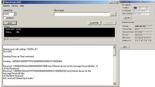
Opto22 PAC SNAP UP1 ADS read network settings using Linux or other OS using a serial port terminal app -
[Other PLC Demo Software] - Opto22 SNAP UP1 ADS read network settings using Linux
Absolutelyautomation posted a topic in Download Comments
View File Opto22 SNAP UP1 ADS read network settings using Linux Opto22 PAC SNAP UP1 ADS read network settings using Linux or other OS using a serial port terminal app Submitter Absolutelyautomation Submitted 04/01/16 Category Other PLC Demo Software -
Version 3.11.2.0
518 downloads
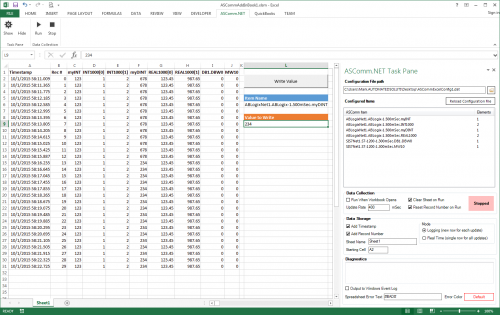
ASComm Excel Add-in is a simple to use, non-programmatic way to populate Excel 2007 - 2021 (version 16) spreadsheets with data from PLCs, instrumentation, and other process hardware. ASComm Excel Add-in uses built-in drivers for Allen-Bradley ControlLogix, CompactLogix, MicroLogix, Micro800, PLC5, and SLC500 communications. No OPC, DDE, external drivers, or programming required. -

[Demo Software] - Excel Add-in for Allen-Bradley Data Logging
Automated Solutions posted a topic in Download Comments
View File Excel Add-in for Allen-Bradley Data Logging ASComm Excel Add-in is a simple to use, non-programmatic way to populate Excel 2007 - 2016 spreadsheets with data from PLCs, instrumentation, and other process hardware. ASComm Excel Add-in uses built-in drivers for Allen-Bradley ControlLogix, CompactLogix, MicroLogix, Micro800, PLC5, and SLC500 communications. No OPC, DDE, external drivers, or programming required. Submitter Automated Solutions Submitted 03/01/16 Category Demo Software -
I have restored a crashed IFIX to a new PC. The restore is ok and installed GE9 driver. With the GE9 power tools, we can observed that data transmits and recieve. The problem is that the screen scada is not updating i.e. no status/feedback, anything is happening. The LAN network TCP/IP was configured i.e. IP, subnet and gateway. Any remedies/advice is most welcome. Please provide a guide on the communication/configuration setup. Thanks
-
Hi all, Quick question about adding ENET modules to a plc. If I have a local network of a HMI, PLC and 1 device all on IP 192.168.255.x and I have another device across the plant with an address of 171.27.19.x, can I add that one device to the PLC and it will recognize it? Is there a way to add a device with a totally different IP address to a PLC that is already set up?
-
Hello: I am new to Connected Component Workbench and Ladder Logic. I am using a ladder with 2 direct contacts on the first rung in series - the first is a N/O switch and the second is a N/C switch how do I make the second direct contact represent a N/C switch. So that someone else looking at my program would know right off the second switch is a N/C switch. Thanks My program functions as it should but the ladder diagram looks like two N/O switches in series.
-
Hello everyone, I need to modify furnace ladder diagram to take control of the upper PID limit. The temperature on the furnace is controlled using PID. There is master PLC CJ1GCPU45SP which communicates several slaves CJ1MCPU13. It looks that all the PID parameters are send from the master to slaves over DeviceNet using seven DRM21 modules installed on extension rack. I can see where the values for the PID are entered on the HMI and moved to new location in the master but I don't understand why they are not placed in memory locations used by DeviceNet by default as per DRM-21 manual ( which if I understand correctly are D30000 to D31599). Is it because the DRM21 are mounted on extension rack? I will list all the upper limit locations in master, it is a long list but hopefully will help in resolving this issue: HMI entry location Moved to location in the ladder D16401 __________________ D32023 D16403 __________________ D32047 D16405 __________________ D32071 D16407 __________________ D32095 D16409 __________________ D32323 D16411 __________________ D32347 D16413 __________________ D32371 D16415 __________________ D32395 D16417 __________________ D32623 D16419 __________________ D32647 D16421 __________________ D32671 D16423 __________________ D32695 D16425 __________________ D29923 D16427 __________________ D29947 D16428 __________________ D31723 D16429 __________________ D31756 D16430 __________________ D31757 D16431 __________________ D31758 After they are moved to the D3xxxx location they are not used anymore anywhere in the master PLC so I am assuming they are transmitted over to be used in slaves. Is my reasoning correct? How can I calculate address space used by each DRM-21 card to make sure I am understanding what is transferred where? Thank you.
-

How to conect RSLogix5000 to 1756 PLC via network
baric1007 posted a topic in Allen Bradley / Rockwell Automation
Hello all, I'm new to this forum, hope I will be able to get some answers on this forum. I'm wotking on maintanance for machines under productiona and I would like to conect one machine to my work PC. But when I try to setup conection with RSLinx, RSLinx don't see my PLC. Problem is that my PC is on network with IP addresses 192.168.8.XXX and machine is on 192.168.0.1 IP address and between is cisco RV180 routher which is set to have LAN address 192.168.8.168 (company network), and WAN is set as 192.168.0.200 (subnet 255.255.255.0, gateway 192.168.0.201, dns 192.168.0.202). When I conect directly 1756 ENBT/A card to my laptop (laptop is set to same range of IP addresses) I can see PLC and everything is working but this way is not practical for me. Is there any way to conect my office PC to PLC, some settings in RSLinx Clasic? Any idea would be helpful. I attached simplified network drawing for easyer understanding. network.pdf Thank you for your time and help, best regards, baric1007 -
I have a Simatic S7-1200 and i have a couple of questions :) I have three analog sensor giving information to the plc. software = Simatic step 7 basic V11 my questions: - can i connect the plc via a cable to a rooter to access the network to use a printer ? -can i connect a SIMATIC HMI KTP400 BASIC COLOR PN via a cable to a rooter to use with the plc via the network? - can i generate a document in the software , add my sensor data and print the document using all of the above ? thanks for all the help :)
-
Is possible to comunicate an Eaton/Cutler Hammer INCOM/IMPACC network with a Modbus network ? Any experience ? Many thanks in advance.
-
hello navigators anyone has ever tried with cx simulator to simulate the network with eternet query from another external PC turns to where cx simulator?
-
Allen-Bradley Logix Family Tag Browser Library for .NET Framework 2.0 - 4.8. ASBrowse.NET
Automated Solutions posted a file in Demo Software
Version 1.1.5
1451 downloads
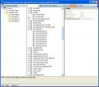
ASBrowse.NET for Allen-Bradley Logix family is a class library for program and tag browsing on A-B Logix family of controllers. View and download any Allen-Bradley Logix Family controller's tag database without RSLogix 5000 or Studio 5000. Can be purchased as ready-to-run application, or as a .NET class library allowing you to incorporate tag browsing into your own applications. Potential uses Quick and easy browsing and verification of programs and tags outside of programming software Runtime tag selection in conjunction with other Automated Solutions products such as ASComm.NET communications driver. Runtime tag selection in conjunction with third party applications or drivers. Bulk edits for importing back into PLC/PAC programming software Documentation Key Benefits Allows you to browse programs and tags on A-B ControlLogix family without the need for RSLogix 5000 Does not require RSLinx or 3rd party drivers Supports controller tags and program tags Supports UDTs and PDTs 100% managed code x86, x64, and Any CPU compatible Visual Studio.NET 2022, 2019, 2017, 2015, 2013, 2012, 2010 (Express, Pro, Premium, and Ultimate Editions) Runtime-free for qualified applications -
Allen-Bradley Ethernet Driver Library for .NET Framework (2.0 - 4.8) - ASComm.NET
Automated Solutions posted a file in Demo Software
Version 3.11.5.0
2804 downloads
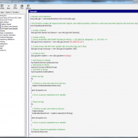
.NET class library for use in Visual Studio.NET to create HMI/SCADA apps that communicate with A-B ControlLogix, CompactLogix, Micro800 Series, PLC5, SLC500, and MicroLogix PLCs via Ethernet. For .NET Framework 2.0 - 4.8 projects. Does not require OPC, RSLinx, or 3rd party drivers. x86, x64, and Any CPU compatible. Visual Studio.NET 2010, 2012, 2013, 2015, 2017, 2019, and 2022 compatible Supports unsolicited messages. Most .NET Framework targets are supported, including Web, Windows, console, and service apps. Can be configured programmatically or visually Visually design your entire communications configuration without writing a single line of code Extremely high performance - 5~10 mSec typical transaction time Supports ControlLogix family native tag names Supports reading and writing entire ControlLogix family UDTs and PDTs Supports block transfers of up to 250 words per transaction Tag database can be configured via code or visual designer Abstract base classes allow you to write generic code that works with all drivers Synchronous and asynchronous read/write methods Data change notifications Provides common user interface across all driver classes No limit on number of devices or data points Multi-threaded for high data throughput Includes extensive help system Example applications with VB and C# source code included. Easily connect office systems to factory floor. Runtime-free for qualified applications -
[Demo Software] - Allen-Bradley Ethernet Driver Library for .NET Framework (2.0 - 4.8) - ASComm.NET
Automated Solutions posted a topic in Download Comments
File Name: A-B Ethernet Driver for .NET File Submitter: Automated Solutions File Submitted: 13 Dec 2007 File Category: Demo Software .NET Component for use in Visual Studio.NET to create HMI/SCADA apps that communicate with A-B ControlLogix, CompactLogix, Micro800 Series, PLC5, SLC500, and MicroLogix PLCs via Ethernet. Supports unsolicited messages Does not require OPC, RSLinx, or 3rd party drivers. x86, x64, and Any CPU compatible Visual Studio.NET 2005, 2008, 2010, 2012, and 2013 Compatible Most .NET targets are supported, including Web, Windows, console, and service apps. Can be configured programmatically or visually Visually design your entire communications configuration without writing a single line of code Extremely high performance - 5~10 mSec typical transaction time Supports ControlLogix family native tag names Supports reading and writing entire ControlLogix family UDTs and PDTs Supports block transfers of up to 250 words per transaction Tag database can be configured via code or visual designer Abstract base classes allow you to write generic code that works with all drivers Synchronous and asynchronous read/write methods Data change notifications Provides common user interface across all driver classes No limit on number of devices or data points Multi-threaded for high data throughput Includes extensive help system Example applications with VB and C# source code included. Easily connect office systems to factory floor. Runtime-free for qualified applications Click here to download this file