Search the Community
Showing results for tags 'high speed counter hsc'.
Found 65 results
-
Hi, I keep getting an error that project is in binary mode and plc is in BCD mode. Wont let me change either. I must be trying in the wrong place...please point me to where i can change this in the PLC. I am getting an error in my RXDU with a Honeywell barcode reader, on one machine, I am thinking it is related. thanks for any help.
-
Hi: I urgently need a simple sample Counter Interrupt Program to study and implement with my machine. I am using GX Work 2 My Problem is inconsistent start stop of roller conveyor after pulse count (OUT_C_32, with cc235, using CC235 to stop a conveyor.) I have to try interrupt, but the manual sample is suck! Please help Tks
-

How to use analog values in SoMachine Basic?
mgn posted a topic in Modicon / Telemecanique / Schneider Electric
I'm using TM221CE40T PLC with TM3DI16 DI extension. I'm programming it using SoMachine Basic. In the program I implemented a counter (%C0). I've read in the documentation that %Ci.V stores the current count value. I want that to display this value on a Magelis HMIS5T. How could I store the current count value (%Ci.V)? Thanks in advance! -
hi: in Omron that is a command to count how many bit that are in ON state, any similar instruction in GX Work 2? Thanks
-
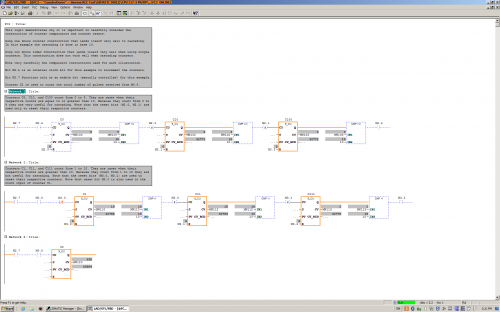
Version 1.0.0
208 downloads
This logic demonstrates the construction and cascading of counters that count from 0 to 9. This logic also illustrates the construction of counters that count from 1 to 10 (not useful for cascading). The difference is mainly in the comparators used to reset the counters. There is one small additional detail. Can you find it? -
View File FC3 Counter Demo This logic demonstrates the construction and cascading of counters that count from 0 to 9. This logic also illustrates the construction of counters that count from 1 to 10 (not useful for cascading). The difference is mainly in the comparators used to reset the counters. There is one small additional detail. Can you find it? Submitter pop29684 Submitted 03/24/16 Category PLC Sample Code
-
Hello, I hope you are all having a great Wednesday. So I was wondering if this is possible, and if so, how to do it. What I'm trying to do is get a real time speed of my hydraulic cylinder using a transducer, a 1769-HSC high speed counter module, and a 1769-L36ERM processor. Kind of like a speedometer in my car. I would like the number in inches/ second. We use a hydraulic proportional valve to control a cylinder that we use to pump molten lead into our die cast machines. Back in the day they used to use limit switched that rest on a tail rod attached to the cylinder shaft to get an approximate stroke length. It was very crude, but it worked for what it was. I'll explain a little more, in case I'm not explaining it very clearly. So on most of our machines the maximum stroke length of a normal shot is about 11". We have different "stages" to the shot. Stage one is typically from 0" (when the shot is all the way returned) until about 1.5", at 1.5" the valve stops and there is a shot delay for 1 second (vacuum draws some lead into the goose neck and into the beginning of the mold), after the delay second stage starts, second stage is from 1.5" to 4", third stage is from 4" to 8" and fourth stage is from 8" to 11.5" or until the shot timer finishes timing, and then another valve switches, and the shot starts it's return. We have the different stages because we typically shoot the cylinder slower at first, and then delay and then almost maximum velocity. We control the velocity with an analog output to a solenoid on a hydraulic valve. For example, for the first stage we may open it up 20%, then 0% during the delay and then 85% during second, third and fourth. Sometimes we play around with different shot delay times, different shot velocities, sometimes 3rd may be faster than 4th, ect, to get the best die casted parts. Anyways, so in the past they would use limit switches. One was a button head style that when the shot cylinder shaft was all the way returned, it made the switch, and we knew the shot was fully returned. One was set at 1.5", 4", 8" etc. They all, except for the shot return switch, were roller style limit switches. They were all made, and once the shot reached that stroke length, they would come off the rod and we would know we were in that next stage. So it was very crude. If you wanted to adjust the stages you would have to climb up on top of the very hot molten lead pot, mark where the limit switch currently was (in case you needed to put it back) loosen the bracket, try to make a measurement and guess how far you moved it. It was crude to say the least. Some of our older style machines that don't need much tweaking still use the limit switch style positioning system. Most of our new machines all use a VisiTrak transducer. The shot cylinder rod that is attached to the cylinder shaft is actually threaded and then has a very thing layer of chrome plating. The transducer sits against the shaft and counts the threads. It transfers those counts to a Very High Speed Counter module in our PLC I/O rack. We have a CompactLogix L36ERM processor and we use a 1769-HSC as the VHS Counter. Then we just do some math in the PLC program and we are able to get shot stroke in inches. We set different compare instructions, for example when: Shot_Stroke is greater than or equal to 0 AND Shot_Stroke is less than or equal to 1.5 then 1st_Stage_Bit is active. We set up different numbers for all the different stages and still use the button head limit switch as a second method to confirm that the stroke is fully returned. The counter is very fast. We are able to know what the shaft stroke is at any given point. We currently do some math using the distance of each stage and using timers to calculate inches per second of each stage. That way we can have a nice Speed number in inches/second that we can use to make different adjustments to the shot. Typically the first stage is about 7"/second second is: 24"/second third is: 42"/second and fourth is 2"/second. But I want a real-time, current speed, not just the speed that it traveled through each of the stages. Ok, after all of that explaining, I'm finally getting to my question. How would I logically write a set of instructions that could give me current speed in inches per second. Like i said, I am able to calculate the speed of each stage, after the shot has completed the stage, I just divide the distance of the stage (in inches) by the time it took to travel through that stage (in seconds). But I would like to have a real time speed, kind of like a speedometer on a car. Is this possible? I know that the scan time on this processor is very fast and the high speed counter module counts very fast as well. How do I do the math to get a real time speed in inches/ second? Sorry for the very long post. I just thought i would give you a background on what we are doing/ would like to do. Thank you very much.
-
PowerFlex 525 overwrite my parameters/ Spd + Strt Problem
charonsk posted a topic in Allen Bradley / Rockwell Automation
Good day, I´m helping with small project and currently i am stuck because of this problem. And I hope you can help me out. I´m using PowerFlex 525 connected with AB CompactLogix 1769-33ER PLC via EtherNet/IP. Connection is working, I can read and write values from/to 525. To configure both devices i´m using RSLogix 5000. 1) First problem occurs after I loaded configuration to 525 and it´s, that 525 keeps overwriting values of Accel and Decel Time 1. It happens when i directly change parameters in Module Properties (online) or after I upload configuration to device. It happens even if i set parameters directly to 525 with its HMI panel. - I kinda get around this problem when i use Accel/Decel Time 2 for Step logic, but if i send direct reference value motor still jump to it and that is not good, especially when changing direction of rotation. 2) Second problem is that I cant get Speed Sources and Start References right. Usually Is working only option 1 and others are not, or they are doing something else that they should. For better imagination this is what i want to do: I have 3-state switch (left = 1 ON(DigIn TrmBlk 02), 2 OFF; center = 1 OFF, 2 OFF; right = 1 OFF, 2 ON(DigIn TrmBlk 03)), In center position I want to control 525 with EtherNet (already working when: Start 1 AND Speed 1 = EtherNet/IP). In left position I want to control motor directly with Drive Pot and In left position a want to start Step Logic (which i have already set) - Funny thing, If I set Start 1 = Ethernet, Speed 1 = Step, Start 2,3 = DigIn, Speed 2,3 = Drive Pot then in all three position motor goes in Step logic.. Or when i get left and right position working then Ethernet is blocked.. and this kind of things.. I Attach print-screen of my current settings, if you need something more just, tell me. Thank you for your time, and I hope someone will be able to help me. -

UnityProXL v8 - Configuring 140-EHC-105-00
RobertJGarget posted a topic in Modicon / Telemecanique / Schneider Electric
Hi all, Currently running a Quantum 140-CPU-652-60 FW3.12 out to a remote rack over a Modbus Drop in to a 140-EHC-105-00 High Speed Counter, words are mapped OK to the program, configured at a type 7 setup (1sec frequency) etc. The card used to work when we were running the system as a ConceptXL 2.6 setup with a 140-CPU-534-14. We have just upgraded to UnityProXLv8 and it stopped. The mapping is configured by word to bit / bit to word across the %IW and %MW (previously 948 3x and 4x registers, but converted nicely, everything is aligning). Anyone stumbled across this issue before? Any help would be appreciated. Thanks, Rob -
This is my company's first time using a Mitsubishi PLC and our partners/clients advised us against using the built-in Ethernet port on the Q03UDE CPU, saying that we should instead use a standalone QJ71E71 Ethernet module. The QJ71E71 costs 1.5x the CPU module so there are significant savings in using the built-in Ethernet. They cited reliability issues but can anyone here back up their claim? We use our PLCs as simple I/O blocks - a PC runs a program which communicates with the PLC and tells it what outputs to fire. There is no actual ladder logic on the PLC. The PC connects directly to the PLC. I wrote a small C# utility that blasts the QX40 and QY80 input/output cards on my stack with random values and reads them back to ensure correct data transfer. The QJ71E71 Ethernet module averages 10 ms for a read or write operation and the Q03UDE averages 3 or 4 ms (much quicker!). So, does anyone have a reason to use the QJ71E71 port instead of the CPU? Thanks
-
Hi Good Day, I need a suggestion, I have an omron encoder, encoder counter meter (K3NC-NB1A) and communication card RS-232C 25pins (K31-FLK1). My question is, what is the best omron software to read and manipulate the data from the encoder (I have CX-one software but I only use CX-programmer). I want to capture the encoder pulse and convert to velocity, acceleration, deceleration and also energy absorbtion. I have to use mathematical formula such as two times differentiation. I also need to show grapf and display final result that is energy absorbtion reading. Or is it much simple if I use VB / labview / java software? Thank you in advance
-
Hello, I need to set a 1 second timer in a TSX 572623 plc with pl7 pro, the question is that using %s6 bit (1 second pulse) the timer is not exact enough, the program is 98 kb, not too big I think, I use the %s6 attaching to a positive pulse auxiliar mark in one section of the program and i use this mark %M in the rest of the program, but as i said, it is not quite exact, measuring the time displayed in a HMI connected to the plc, 40 seconds in the program (displayed in a HMI), it´s 47 seconds in a chronometer, it is not exact at all as I said, how can I solve this problem, can anyone help me? Thanks
-
Hi I need to program my fatek fab Plc with the following : . I need to detect between a single long input or a repeated second pulse. The idea is to control a window blind with two outputs of the Plc and two inputs (one for up, from a up switch and another for down from the down switch). the blind should go up until I maintain the key pressed. But when I make a repeated two pulse on the key it should go up automatically during a certainly define time (enough to completely open the blind). The same for the down direction. I need help on that.
-
i am using CP1E cpu . i wants to use increment counter . if i use CNT instruction it was counteing decrement count . anybody can share the instruction for same satheeshkumar
-
Hello guys, i would like to know if is possible keep always active the run command in a vf drive and for stopping the motor only send 0 reference. It´s possible??? because I want to program a ramp function in my plc for start and stop one motor. could someone tell me how to do this type of control please?.