Search the Community
Showing results for tags 'function block enable bit ladder logic missing'.
Found 162 results
-

"Ladder Logic" internal contact set-up
MikeOrsini87 posted a topic in Modicon / Telemecanique / Schneider Electric
Hi Everyone, I'm working on my first PLC program and I have gotten my hands on some ladder logic I'm trying to duplicate. I'm using SoMachine 4.1 and have started a new Ladder Logic diagram POU. I'm curious on how do I create internal contacts. EXAMPLE: 24v--------l START BUTTON l----------------( COIL A)----- --------------l COIL A CONTACT 1; attached to a real output, solenoid valvel-------------l COIL A INTERNAL CONTACT TO CLOSE l---------------- Are there standards for numbering and labeling? I'm seeing L and U inside coil contacts. Does this have an underlying meaning according to standard? Is there a RTO function inside SoMachine 4.1 -
Ladder Logic socket communication
Br4zzor posted a topic in Modicon / Telemecanique / Schneider Electric
Hi everyone, I'm a newbie in the ladder logic programming languages. For my thesis project I've to develop a scenario but I'm stuck with the creation of a socket connection from the Modicon M340 PLC to a server for transfer continuous data given from sensors or similar. Does anyone have a sample program that could have such a functionality so that I can change it based on my needs? Thanks in advice for any further reply! -
Hi All, I'm still quite new to Unity and Modicon PLCs. I have a PLC program running in simulation mode for development/test and I'd like to follow the logic inside a running block. I can't seem to just double click the function block while online to see it's 'inside' logic. Is there a way to inspect the inside of a running function block? How can I check and diagnose the logic a running function block? Thanks!
-
Good morning folks, I've browsed this forum often enough over the past few years that I think it's time I finally signed up. Lots of good ideas and advice that I've benefited from and I hope to return the favour some day. So on to my question.... I'm currently knee deep in a project using a CJ2M PLC and I have to send and receive chunks of data over Ethernet/IP. To do this, I'm using the ESATR and EGATR commands (set / get attribute). I would like to know if these commands finish execution (ie. the ethernet port completes the transaction) even if the input conditions to the command are no longer true. Specifically, if I use the "port ready" system flag (A202.00 is an input to my FB in this case) as a condition to trigger the ESATR command, this bit will go low once the port becomes busy (ie. during execution). So will that interrupt the completion of the ESATR command resulting in an incomplete transaction and data loss? I've looked through the help files on the command but don't get a clear picture of how it behaves. Perhaps the attached JPEG shows more clearly what I mean. Thanks, PC
-
Hello, I am currently working on programming my first sortation system. Attached is a blue print of the in feed conveyors and their loadout lines. As boxes merge together they will be scanned by the barcode scanner. From there we will be told which lane each box must go down, from the WCS. My question is, without encoders, what would be the best way to control this system? Counting the packages as they pass through the photoeye? Or setting timers? Thanks, James Sorting Conveyor Layout.pdf
-
Dear Experts, I have been trying to activate FX2N-2LC temperature control block but nothing could help. I have tried the ladder logic which is available in Mitsubishi manual but this is not any output from the module. Please help me or guide me to get rid over this problem, I am attaching the ladder diagram so you guys will get the Idea to where I am going wrong. FX2N-2L Program.pdf
-
PLC 5 ladder output unexpected behavior
wdfiller posted a topic in Allen Bradley / Rockwell Automation
I hate to start a new topic on such an old processor but I forced to keep this thing working until I can upgrade it. We are having funny issues with outputs. At first they were on a PLC5/60. We suspected a bad processor so we changed to a PLC5/40 we had in our tool crib and the problem didn't go away. Some of our outputs in the ladder are being evaluated to true but not turning on. We can force the output on and it will come on and when we remove the force it will turn back off. I've never seen this problem before on any processor. All the logic leading up to the output is true but the output is not turning on and is there not green. I've already checked all the obvious causes. The instruction is an OTE. The output is not duplicated somewhere else in the logic that is turning it off. The ladder file is being scanned. I replaced the output with a B3 bit and on the next line had the B3 bit turn on the ouput. The B3 output bit turned on but the output did not. This output is on a remote I/O rack and other outputs on that rack are working. Any ideas would be greatly appreciated. -
CAN SOMEONE PLEASE SUGGEST ME ONE OF THE BEST ONLINE LADDER LOGIC SIMULATOR OR SIMULATOR SOFTWARE FOR PRACTICING AND DEVELOPING LADDER LOGIC SKILLS.??
-
Hi, can you help me how to make program indirect address for plc omron? I use PLC CP1E Thanks
-
Version 1.0.0
560 downloads
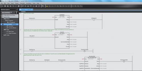
This is a very simple ladder program that shows the basic steps to enable, zero and move a 1S servo using the NJ controller. -

[PLC Sample Code] - Basic Servo Control Code for NJ and 1S
Michael Walsh posted a topic in Download Comments
View File Basic Servo Control Code for NJ and 1S This is a very simple ladder program that shows the basic steps to enable, zero and move a 1S servo using the NJ controller. Submitter Michael Walsh Submitted 02/10/17 Category PLC Sample Code -
Can Anyone Come Up with the Screen Shots or a video link of procedure for Displaying Real Time Sinusoidal Waveforms From Satec MFM ON GE FANUC?? I have PACsystem RX3i via Serial Communications Module-IC695CMM002
-
can you help me? bring me some example to build function block program with Gx Works? I use Q02U CPU thanks
-
Hello, Im looking for the in built function blocks, but i cannot find it in the program files/ omron folder where the manual says (even with search for *.cxf), perhaps i dont have it installed, but where can i get them from? As i remember i downloaded cx-one from the official omron web page after login etc, so thats why i dont understand why am i missing the fb libraries What else place there is to find useful FB-s? Thanks!
-
Hello. A colleague sent me a screenshot (attached) with a peculiar issue. An ADD function that only sends 0 as the outcome, and a DTOS function that only sends " . I have confirmed that all variables used in the ADD block are declared as integers, and both SumInt6 and String10 are not currently being modified somewhere else. This impatient colleague is baffled, while I am just sharing this issue in the hopes that someone will eventually come with the simple answer that we are overlooking, or a complex one that we could never hope to realize by ourselves. Thanks in advance.
-
Hi! Anyone can help regarding this issue. I'm not able to monitor the Motor Block that I have created. there's no error either in the output screen but i'm thinking what is the cause of not running in the simulation which shows the Motor Folder RED even it was compiled. thanks for the help! Note: I'm new in mitsubishi.
-
Hello everyone! Could someone help me and explain me this block of a ladder diagram I'm working with? I do understand the M800 is always ON contact, for the PLC to not lose the values. Also I know that the DIV is a division, the FLT is a integer to floating point (thing I don't understand), the DEMUL is a floating point multiplication (thing I also don't understand), the INT is a floating point to 16-bit integer, and the MOV is for moving a value from a data register to an other data register. Help... :(
-
how to make looping in ladder logic? but i want to make the data +1 each time until 3 and return back to 0 after reaching 3.
-
Hi all, I would like to monitor the status of my alarm word (MW100) and if any bit turns from 0 to 1 then an alarm signal should be generated, am new to siemens plc and am having a tough time accomplishing this easily. In omrom CX programmer its quite easy to do. Could anyone help me on this using ladder logic, all help will be deeply appreciated. Regards, Ablex PS: I'm using Step 7 V5.5
-
Hi, i want to make a function block which will contain a block GP.CPRTCL (for predefined comm protocol). GP.CPRTCL has an input "Un" who only receives constant (H,K). On input of my own function block i can set a constant variable, but inside block that variable isn't a constant anymore (GP.CPRTCL doesn't recognize a variable). Is there a way for receiving constant variable in GP.CPRTCL block ("Un") if it is in another block. Regards
-
Hi everyone, I need some help with my PLC programming. I am currently using a twincat 2 software and a Beckhoff CX 8090. Basically, the gist of my program is to send and receive data and datalog the input data received from the sensors and timestamp the received data for every 1 second. I want to create a boot up counter where it will count the number of times my data logging program has restarted(if it did). This boot up counter serves as a health monitoring check to ensure that my program is running perfectly and thus, not restarting randomly when it shouldn't. I am more familiar with structured text so if you have a solution, kindly post it in structured text form. Your help would be greatly appreciated. Best regards, DeadPool
-
Hi guys, I'm in the middle of a little university project, I'm attempting to implement a control system purely based on artificial intelligence. A neural network will be used to map the characteristics of a power plant. A fuzzy logic controller will be used instead of the conventional PID and finally a genetic algorithm will be used to tune the controller while the system is online. This is all simulated of course. Each of those AI's will be developed in Matlab. Only problem with that is, is it outputs the code in C or C++ (From memory). I would have to convert this to structured text (Based on Pascal). So to circumvent this problem I thought I would just directly interface matlab to the PLC (Schneiders M340). My idea being, all the calculations are done in matlab which are then sent back to the PLC. However this presents me with a new problem of how I would be able to interface matlab to the PLC. If anyone has experience with this sort of connectivity, any advice would be greatly appreciated. Thank you in advance, Luchek
-
Hello, I got a new work job to design a cycle tester for a mechanism to make sure will work for at least 5000 cycles open - close. I never made a pls program I start researching few days ago and seams to be very complicate to make it. I have a TM221C16R PLC from Schneider. please help me with some instructions. the cycle tester will have a start pushbutton, stop pushbutton, door open switch, one air cylinder with solenoid to push and pull and a counter. Thank you, Romica
-
Hello. I'm trying to use index addressing inside function block. The command *D200 doesn't work. Is it necessary to use IR0, ID0,... inside function block? Thanks. Best regards
-